
User's Manual


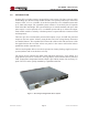


Table Of Contents
- 1.0 INTRODUCTION
- 2.0 FEATURES & OPTIONS
- 3.0 SAFETY WARNINGS
- 4.0 WARRANTY (summary)
- 5.0 UNPACKING AND INSPECTION
- 6.0 GENERAL SPECIFICATIONS
- 7.0 PRINCIPAL OF OPERATION
- 8.0 FRONT PANEL DESCRIPTION
- 9.0 REAR PANEL DESCRIPTION
- 10.0 LED Indicators
- 11.0 MAKING CONNECTIONS TO THE X75
- 12.0 INSTALLATION
- 13.0 USING THE CONTROLLER WEB BROWSER INTERFACE
- Appendix 1 – SNMPv3 MIB Information
- Appendix 2 – Load LVD (special order)
- Appendix 3 – Revision History
- Figure 1 - X75 Compact Integrated DC Power System
- Figure 2 - Block Schematic
- Figure 3a - Front View with Breakers (configuration A)
- Figure 3b - Front View with GMT Fuses (configuration B)
- Figure 4 - Rear Views of Base and Expansion Units
- Figure 5 - LED Indicators
- Figure 6 - Recommended Load Circuit Wire Sizes
- Figure 7 - Battery Temp. Probe & Alarm Relay Connector Pin-Out
- Figure 8 - Ethernet Connector Pin-Out
- Figure 9 - Auxiliary Connector Pin-Out
- Figure 10 - Input Current Ratings
- Figure 11 - Status WEB Page (typical)
- Figure 12 - Rectifier Status WEB Applet (typical)
- Figure 13 - Installation WEB Applet - system tab (typical)
- Figure 14 - Installation WEB Applet - float & tc tab (typical)
- Figure 15 - Installation WEB Applet - battery tab (typical)
- Figure 16 - Installation WEB Applet - float & tc tab (typical)
- Figure 17 - Installation WEB Applet - lvd tab (typical)
- Figure 18 - Installation WEB Applet - digital i/p tab (typical)
- Figure 19 - Installation WEB Applet - rectifiers tab (typical)
- Figure 20 - Installation WEB Applet - shunts tab (typical)
- Figure 21 - Battery Management WEB Applet (typical)
- Figure 22 - Alarm Matrix WEB Applet (typical)
- Figure 23 - Alarm Matrix WEB Applet - matrix options (typical)
- Figure 24 - Alarm Matrix WEB Applet - temperature alarm settings (typical)
- Figure 25 - Alarm Matrix WEB Applet - voltage alarm settings (typical)
- Figure 26 - Alarm Matrix WEB Applet - voltage alarm settings (typical)
- Figure 27 - Alarm Matrix WEB Applet - other alarm settings (typical)
- Figure 28 - Network Settings WEB Applet (typical)
- Figure 29 - Alarm Log WEB Applet (typical)
- Figure 30 - Data Log WEB Applet (typical)
- Figure 31 - Change Password WEB Applet
- Figure 32 - Help WEB Page
- Figure 33 - About WEB Page (typical)

Page 4
X75 SERIES - Mk3 Controller
INSTALLATION & OPERATING MANUAL
Manual No. x75mk3-11
x75-man-Rev11-0815.indd
1.0 INTRODUCTION
Gravitas X75 is an ultra-compact, integrated DC power system. The base system is a 1RU
shelf holding up to three hot-swap rectier modules. This system produces up to 1950 watts
output at -54.4, +27.2 or +13.6VDC. It can also be operated as a 2+1 redundant system with
up to 1300 watts output. The expanded system consists of a base shelf plus an expander
shelf with a 2RU total height. This system holds up to six rectier modules with up to 3900
watts output; it can be operated as a 5+1 redundant system with up to 3250 watts output.
Each rectier module is cooled by a fan that operates at a speed which is a function of load
and temperature.
There are up to ve circuit-breaker protected DC outputs or up to 10 GMT fuse protected
outputs on the base system. A battery string breaker and a low-voltage battery disconnect
are standard features. The expander shelf comes with a ribbon cable and connectors to link
the signals between the two units at their rear panels. It also comes with bus bar links to
parallel the rectier output bus bars.
The base and expander shelves can also be operated as a battery backup, single feed power
system (without load circuit breakers or fuses).
The remote access controller has LED visual indicators and Form C relay alarms. It is
programmed by means of a remote PC web page display with communication by Ethernet
LAN. Temperature compensated rectier output is provided by means of an accessory TC
probe. The X75 can be quickly installed by a qualied technician.
.
Figure 1 - X75 Compact Integrated DC Power System