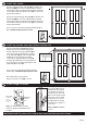
Ad va n ce d S c re e n Sys te m s Surface Mount Ad va n ce d S c re e n Sys te m s Ultimate Double Security Screen Door Kit Installation Instructions Ad va n ce d S c re e n Sys te m s Ad va n ce d S c re e n Sys te m s DISREGARD INSTRUCTIONS INCLUDED WITH DOOR PANELS • • • • • Ad va n ce d S c re e n Sys te m s Read completely through the kit installation instructions before proceeding with installation Installation requires two people Use appropriate protective equipment, including safety glasses
SINGLE DOORS (2) NOTE: Not all parts from single doors will be used for a double door configuration. C B) Hinge-side jambs (2) B1) Hinge-side snap covers (2) C) Security screen doors (2) H) Hinges (6) & fasteners (36) O) Locking handles (2 pc) P) Lock cylinder & flat-head bolt (1) J) #10x2-1/2" flat-head screws (24 pcs.
1 Determining Identify and prepare Your Build mounting Out Area surface (continued) Inspect Your Entryway for Obstructions Check for any obstructions above and around your entryway that may prevent the outward swing of your new security door, and/or its installation, such as: • Light fixtures • Low overhang • Door bell • Trees, bushes, or hanging plants Determine Type and Readiness of Mounting Surface Your new security door will require a minimum mounting surface of 1" on the trim above, and on both si
1 2 Determining Determine your Your threshold Build Out configuration Area (continued) Look at your existing entry door threshold and use the diagrams below to determine which threshold configuration best applies to your entryway. This will determine whether a bottom bar is or is not required for your security door. Bottom Bar Required 1 3 Bottom Bar NOT Required The concrete is set back and lacks space to mount to the threshold plate. The concrete extends at least 7/8" further than your trim.
1 5 Determining Install side jambs Your Build Out Area (continued) Place the active door hinge-side jamb (B) into position over bottom bar (DD).Be sure that it is plumb and level against the mounting surface. Install using two temporary mounting screws (#6x2" temporary drywall screws (K)) one at the top and one at the bottom. Place the inactive door hinge-side jamb (B) into position over bottom bar (DD).Be sure that it is plumb and level against the mounting surface.
8 Determining Prepare inactive Yourdoor Build Out Area (continued) 1 2 Remove the mounting screws on all three locks of the inactive door. 9 Lift the one-piece gear up and out of the edge of the door. Set aside. Determining Install astragal Your on Build inactive Outdoor Area (continued) Place the astragal (CC) on the inactive door so the top edge is even with the top edge of the door panel. Clamp in place. Attach the astragal (CC) to the inactive door using four #8x1-1/2" flat-head screws (NN).
11 Install Determining bottomYour shoot Build boltOut in astragal Area (continued) Slide the shoot bolt (HH) into the astragal (CC) at the bottom of the inactive door. Retract the shoot bolt by pulling up on the lever and position shoot bolt flush with the bottom of the astragal. In the exposed top mounting hole of the shoot bolt (HH) attach using #8x1" silver flat-head screw (MM). Deploy the shoot bolt lever to expose the bottom mounting hole attach using #8x1" silver flat-head screw (MM).
14 1 Install Determining active Your door Build handle Out and Area lockset (continued) 1) Start on the interior side of the door. With the handle (O) facing toward the screen, insert the spindle and mounting screws through the mortise gear in the door panel. 2) Move to the exterior of the active door. With the handle pointing toward the active door panel hinges, align the openings on the inside of the other handle (O) with the spindle and 2 mounting screws and position the handle against the door frame.
17 Adjust Determining and align Yourtop Build reveal Out Area (continued) Close both the active and inactive doors. Both doors should align at the top with an even reveal. If adjustment is necessary loosen (do NOT remove) the top temporary jamb screws from each side jamb. Use a rubber mallet to tap the right or left side jamb so doors become aligned. Re-tighten temporary screws.
21 Install Determining threshold Yourplate Build Out Area (continued) 2 1 Existing door contour 3 Mark center hole 4 5 Make cardboard template Fit template to contour Cut template to contour 6 7 Mark threshold plate Cut threshold plate to fit 1 The contour of door framing varies, making it necessary to cut the threshold (EE) to fit. We recommend cutting a cardboard template to fit the opening first, to avoid cutting the threshold incorrectly.
24 Install Determining latch guard Your Build Out Area (continued) 1. Remove screws from the one-piece gear. One-piece gear Latch guard 3. Attach the latch guard (BB) provided in the hardware box using six #8x1" painted flat-head screws (MM) in the pre-drilled holes. 2. Hold or clamp latch guard in place even with the top of the active door aligning with the pre-drilled mounting holes in the door panel (C).
Final touch-up suggestions 1 Caulk (not included) Caulk around the outside of the security door jamb frame, using paintable caulk, and paint to the desired color. 2 White Grease Lubricant (not included) Use white grease to lubricate the hinges of your new security door. Care and maintenance Over time, airborne dust, dirt, and impurities can accumulate, which will cause visual defects to your Meshtec screen and, if not regularly and properly removed, can lead to further damage, staining, and corrosion.
Ad va n ce d S c re e n Sys te m s Instalación sobre superficie Ad va n ce d S c re e n Sys te m s Instrucciones de instalación del kit de puerta con doble malla de seguridad última Ad va n ce d S c re e n Sys te m s Ad va n ce d S c re e n Sys te m s IGNORAR INSTRUCCIONES INCLUIDAS CON LOS PANELES DE LA PUERTA Ad va n ce d S c re e n Sys te m s • • • • • Lee todas las instrucciones de instalación del kit antes de la instalación La instalación requiere de dos personas Usa el equipo de protección ap
CAJAS DE PUERTAS (2) Nota: No todas las piezas de una puerta sencilla se usarán al instalar una doble. B) Jambas del lado de las bisagras (2) B1) Cubiertas a presión del lado de las bisagras (2) C) Puertas con malla de seguridad (2) H) Bisagras (6) y sujetadores (36) O) Manijas de cierre (2) P) Cilindro de cerradura y perno de cabeza plana (1) J) Tornillos de cabeza plana núm 10x2-1/2” (24 pcs.
1 Determining Determina y prepara Your Build la superficie Out Area (continued) de montaje Revisa si hay obstáculos en la entrada Comprueba si arriba o alrededor de la entrada hay obstáculos que puedan impedir la instalación de la nueva puerta de seguridad o su abertura hacia afuera; obstáculos como: • Lámparas • Salientes bajos • Timbre de puerta • Árboles, arbustos o plantas colgantes Determina el tipo y el estado de la superficie de montaje Tu puerta de seguridad necesita una superficie de montaje d
1 2 Determining Determina la Your configuración Build Out de Area tu (continued) umbral Observa el umbral de tu puerta de entrada actual y usa los diagramas más abajo para determinar cuál es el umbral adecuado para tu entrada. Esto determinará si necesitarás o no instalar una barra inferior en tu puerta de seguridad. Requiere la barra inferior NO requiere la barra inferior No hay espacio en la superficie de concreto para montar la placa del umbral.
1 5 Determining Instala las jambas Your Build laterales Out Area (continued) Coloca la jamba (B) del lado de las bisagras de la puerta activa en su sitio sobre la barra inferior (DD). Verifica que esté a plomo y nivelada contra la superficie de montaje. Instala con dos tornillos de montaje temporal para drywall núm. 6x2" (K), uno en la parte superior y otro en la inferior. Coloca la jamba (A) del lado de las bisagras de la puerta inactiva en su sitio sobre la barra inferior (DD).
8 Determining Prepara la puerta Your inactiva Build Out Area (continued) 1 2 Quita los tornillos de montaje en las tres cerraduras de la puerta inactiva. 9 Levanta el mecanismo de una pieza y sácalo del borde de la puerta. Ponlo a un lado. Determining Instala el astrágalo Your Build en laOut puerta Areainactiva (continued) Coloca el astrágalo (CC) en la puerta inactiva de forma tal que el borde superior esté nivelado con el borde superior del panel de la puerta. Fíjalo en su lugar.
11 Instala Determining el pestillo Yourcon Build resorte Out Area inferior (continued) en el astrágalo Desliza el pestillo con resorte (II) dentro del astrágalo (CC) en la parte inferior de la puerta inactiva. Retrae el pestillo con resorte halando la palanca; coloca el pestillo con resorte al ras con la parte inferior del astrágalo. Fija en el orificio de montaje superior expuesto en el pestillo con resorte (HH) usando un tornillo de cabeza plana plateado núm. 8x1" (MM).
14 1 Instala Determining la manija YouryBuild la cerradura Out Area de(continued) la puerta activa 1) Comienza desde la parte interior de la puerta. Con la manija (O) de frente a la malla, inserta el eje y los tornillos de montaje a través del mecanismo de mortaja en el panel de la puerta. 2) Muévelo hacia el exterior de la puerta activa.
17 Ajusta Determining y alinea Your el espacio Build Out deArea reborde (continued) superior Cierra ambas puertas, la activa y la inactiva. Ambas puertas deben alinearse en la parte superior con un espacio de reborde nivelado. Si no se requiere ajustar, afloja (SIN quitar) los tornillos temporales superiores de las jambas laterales. Usa un mazo de goma para dar unos golpes en la jamba lateral izquierda o derecha para alinear las puertas. Vuelve a ajustar los tornillos temporales.
21 Instala Determining la placa Your delBuild umbral Out Area (continued) 1 2 3 4 5 Contorno de la puerta actual Marca el orificio central Hacer las plantillas de cartón Ajustar la plantilla al contorno Recortar la plantilla por el contorno 6 7 Marca la placa de umbral Corta la placa de umbral a la medida 1 El contorno de los marcos de las puertas varía, por lo tanto es necesario recortar el umbral (EE) a la medida.
24 Instala Determining el protector Your Build del pestillo Out Area (continued) 1. Quita los tornillos del mecanismo de una pieza. Mecanismo de una pieza Protector del pestillo 3. Fija el protector de pestillo (BB) incluido en la caja de herrajes insertando seis tornillos de cabeza plana pintados núm. 8x1" (MM) en los orificios pretaladrados. 2.
Sugerencias de retoques finales 1 Pasta selladora (no se incluye) Aplica pasta selladora para pintar en el exterior del marco de la jamba de la puerta de seguridad y pinta del color deseado. 2 Lubricante de grasa blanca (no se incluye) Cada seis meses, lubrica con grasa blanca las bisagras de la puerta de seguridad nueva.