
Installation Guide


47
20/24”
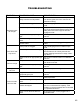
WIRING DIAGRAM
N L
OVEN WIRING DIAGRAM
Circulating
fan switch
Burner
controller
Burner
controller
Burner
controller
Bidirectional
controller
Burner
controller
Flashlight
1 3
2 4
1 3
2 4
switch
Circulation
fan
Flashlight
Terminal
block
线路图标贴 200*200mm
/ SCHÉMA DE CÂBLAGE DU FOUR
Interrupteur du
ventilateur à
convection
Pulse Igniter
Contrôleur
du brûleur
Contrôleur
du brûleur
Contrôleur
du brûleur
Contrôleur
du brûleur
Contrôleur
bidirectionnel
Allume-gaz à
impulsions
Bornier
Lampe clignotante
Ventilateur à
convection
Interrupteur
de lampe
clignotante
The gas appliance regulator must be set for the gas with which the
appliance is used (NG Gas). Orifices for LPG conversion can be found
with the manual package. See installation instructions for complete
conversion information.
NG
GN