PRESTIGE GAS RANGE (NG & LPG convertible) UGP-20V PC1 S/S UGP-20V PC1 W UGP-20V PC1 B INSTALLATION AND OWNER’S MANUAL 20” (50.
UNIQUE 20” PRESTIGE MODEL GAS RANGE - NG & LPG CONVERTIBLE Installation & Owner’s Manual This manual contains information for: Important Safeguards Installation Use and Care Certain ranges come equipped with special features. Determine from a study of your range which of the instructions given in this booklet pertain to your range. This booklet gives valuable instructions covering the installation, adjustment and use of your range.
MANUFACTURED & CERTIFIED BY Unique Gas Products Ltd X2 2245 Wyecroft Road #5 Oakville, Ontario, Canada L6L 5L7 Ph: 905-827-6154 Toll Free: 1-877-427-2266 Fax: 905-827-2027 www.UniqueOffGrid.
UNIQUE GAS RANGE Table of Contents 05 14 15 16 17 20 22 27 30 36 37 39 44 46 47 47 48 49 52 53 4 Important safety instructions Energy saving ideas Installation instructions How to install the backsplash Gas connections Wall clearances Gas range conversion Adjusting the top burner and oven flame Operation of range Alignments and adjustments Cleaning the range Care and maintenance Troubleshooting Wiring diagram Contact us Warranty Parts diagram Parts list Appliance information Notes
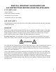
BEFORE USING YOUR GAS RANGE WARNING HAVE THIS RANGE INSTALLED BY A QUALIFIED INSTALLER. Improper installation, adjustment, alteration, services, or maintenance can cause injury or property damage. Consult a qualified installer, service agency, or the gas supplier. BEFORE USING YOUR GAS RANGE: • Remove the exterior and interior packing. • Remove the protective film on steel and aluminum parts. • Check to be sure you have all of the parts listed below.
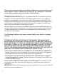
Welcome & Congratulations Congratulations on your purchase of a UNIQUE range! We are very proud of our product – and are completely committed to providing you with the best service possible. Your satisfaction is our #1 priority. Please read this manual very carefully. It contains valuable information on how to properly maintain your new Unique gas range. We know you will enjoy your new range and Thank You for choosing one of our Unique Gas Products! We hope you will consider us for future purchases.
READ ALL IMPORTANT SAFEGUARDS AND ALL INSTRUCTIONS BEFORE USING THE APPLIANCE. IF YOU SMELL GAS: • Open windows • Don’t touch electrical switches • Extinguish any open flame • Immediately call your gas supplier FOR YOUR SAFETY: • Keep appliance area clear and free from combustible materials gasoline and other flammable vapors and liquids. WARNINGS Destroy the carton and plastic bags after the range is unpacked. Children should not use packaging material for play.
Notice: Never keep pet birds in the kitchen. Birds have a very sensitive respiratory system. Fumes released from cooking oil, fat, margarine or overheated non-stick cookware may be harmful or fatal to birds. PROPER INSTALLATION: Be sure a qualified technician in accordance with the National Fuel Gas Code ANSI Z223.1/NFPA54 properly installs your appliance. Install only per installation instructions provided in the literature package for this range.
USER SERVICING: Do not repair or replace any part of the appliance unless specifically recommended in this owner’s guide. Only a qualified technician should do all other servicing. This will reduce the risk of personal injury and damage to the range. Storage in or on appliance: Flammable materials should not be stored in an oven, near surface burners or in the broiler section. This includes paper, plastic and cloth items, such as cookbooks, plastic ware and towels, as well as flammable liquids.
Do not use water or flour on grease fires. Smother the fire with a pan lid, baking soda or use a dry chemical or foam-type extinguisher. Operation of the Surface Burners. When the burners are operated for the first time, a small amount of smoke may be generated due to tape residue or manufacturing lubrication, this is not dangerous. Operate the burners for about five minutes to rid the burners of this material before cooking. Use only dry potholders.
Cookware handles should be turned inward and not extend over adjacent surface burners. To reduce the risk of burns, ignition of flammable materials, and spillage due to unintentional contact with the cookware, the handle of a cookware should be positioned so that it is turned inward, and does not extend over adjacent surface burners. Never leave the surface burners unattended. Boilovers may cause smoking, greasy spill-overs may catch fire or a pan which has boiled dry may melt.
Flexible Connectors: If the gas range/oven is connected to a gas supply with a metal flexible connector, move the range/oven with CAUTION for service or cleaning. Flexible connectors are not intended for repeated bending. Do not allow cleaners to make contact with flexible connectors. The connector and its fittings are designed for use only on the original installation and are not to be reused for another appliance or at another location. Connectors must comply with ANSI Z21.24.
CARBON MONOXIDE WARNING: Carbon Monoxide is a possible danger when using any gas powered appliance. All gas appliances MUST be installed by a licensed professional who is familiar with the Carbon Monoxide levels appropriate for each appliance. The American Gas Association publishes CO emissions for appliances and heating equipment through the ANSI Std. Z21.1 The EPA reports that a maximum CO (Carbon Monoxide) level of 9 PPM over a 24 hour period is the residential interior ambient level standard.
ENERGY-SAVING IDEAS Surface Cooking Use lids when surface cooking. A lid traps steam and uses it to speed up the cooking process. If you have a pressure cooker or vegetable steamer, use it. You’ll waste fewer vitamins, save time and cut energy costs. Use medium-weight, flat bottomed pans that match the flame size. Choose pans made of metals that conduct heat well. When cooking on a surface burner, use as little water as possible to reduce cooking time.
INSTALLATION INSTRUCTIONS Be sure appliance is properly installed and grounded by a qualified technician. It is the responsibility of the technician to make certain that your range is properly installed. Situations caused by improper installation are not covered under the warranty. Any expenses incurred due to such situations will not be paid by the manufacturer of the appliance. A child or adult can tip the range and be killed. Install the anti-tip device to the structure and/or the range.
HOW TO INSTALL THE BACKSPLASH 1. Align the backsplash to the rear part of the cooktop as shown in the diagram. 2. Secure the backsplash to the cooktop from the back using the 2 Philips head screws provided as shown in the diagram. 3. Secure the backsplash from the bottom using the Philips head screws provided as shown in the diagram.
GAS CONNECTIONS (All Units) NOTICE TO MASSACHUSETTS APPLIANCE DEALERS: Be sure this document is included in all gas range appliances sold to consumers in the State of Massachusetts. NOTICE: Massachusetts law requires the following: • Appliances must be installed by a licensed plumber or gas fitter. • Appliances must be connected with a three (3) foot (36” maximum length) flexible gas connector and • A “T” handle type manual gas valve in the gas supply line to the appliance.
GAS CONNECTIONS (continued) The appliance and its individual shut-off valve must be disconnected from the gas supply piping system during any pressure testing of that system at test pressures in excess of 1/2 psig. The appliance must be isolated from the gas supply piping system by closing its individual manual shut-off valve during any pressure testing of the gas supply piping system at test pressures equal to or less than 1/2 psig.
GAS CONNECTIONS (All Units) When using this on LPG gas, conversion must be made by a qualified LPG installer before attempting to operate the range on that gas. For correct operation, the pressure of natural gas supplied to the regulator should be between 4” and 5” of water column. For LP gas, the pressure supplied must be between 10” and 12” of water column.
WALL CLEARANCES All units must be installed in accordance to minimum rear and side wall clearance and clearances extended vertically above cooking top which are stated on the serial plate located at the back of the range. ANY OPENINGS IN THE WALL BEHIND THE UNIT AND IN THE FLOOR UNDER THE UNIT MUST BE SEALED. Note. Due to potential hazards it is recommended that storage cabinets NOT be installed above the cooking surface.
WALL CLEARANCES (continued) 21
GAS RANGE CONVERSION To convert application and/or adjust from NG to LPG The range is set for use with Natural Gas (NG). The factory setting is indicated on the serial plate. When set for Natural Gas operation, the pressure regulator will regulate the gas to 5 inches water column pressure. When set for Liquid Propane Gas (LPG) operation, the pressure regulator will regulate the pressure to 10 inches water column.
GAS RANGE CONVERSION MODEL NUMBER: UGP 20V PC1 S/S, UGP 20V PC1 W, UGP 20V PC1 B Parts List: 1. Orifices 2. Screwdriver UGP 20V PC1 S/S UGP 20V PC1 W UGP 20V PC1 B NOZZLE (LPG) RL 2” 0.68 FL 0.9 BROILER 0.8 OVEN 0.82 RR 1.0 FR 0.53 2” Convertible Pressure Regulator The range is shipped to operate on NG. LPG orifices and a special screwdriver for adjusting the minimum flame are shipped with the unit in a separate envelope with the manual.
GAS RANGE CONVERSION LPG NG 5. Using an adjustable wrench replace the cap back on the regulator, do NOT over tighten cap. 6. Remove the grates, burners and burner caps from the range to access the orifices. 7. Use a 7mm wrench to remove the orifices. Each orifice can be located in the center of the burner base - see fig 2 Burner Orifice fig 2 8. Remove all NG orifices, place in the bag and store in a safe place. 9.
GAS RANGE CONVERSION To replace the broiler burner orifice 1. Remove the back panel 2. Locate/disconnect broiler orifice housing screws x 2 (Fig 1) BROILER 3. Gently bend gas tube to gain access to the orifice 4. Use a 7mm socket to remove orifice and replace with specified orifice for gas conversion 5. Remount broiler orifice housing screws x 2 OVEN To replace the oven burner orifice 1. Locate/disconnect oven orifice housing screws x 2 2. Gently bend gas tube to gain access to the orifice (Fig 2) 3.
GAS RANGE CONVERSION CHECKING FOR MANIFOLD GAS PRESSURE To check the manifold gas pressure, remove the burner cap and connect a manometer (water gauge) or other pressure test device to the burner orifice. Use a rubber hose with inside diameter of approximately ¼” hold the end of the hose tight over the orifice. Turn the gas valve on. For a more accurate pressure check, have at least two (2) other top burners burning.
ADJUSTING THE TOP BURNER AND OVEN FLAME Keep appliance area clear and free from combustible materials, gasoline, and other flammable vapors and liquids. Do not obstruct the flow of air that is necessary for combustion and ventilation. Top Burner Valves The top burners have orifices that are dedicated to the type of fuel to be used. These orifices are not adjustable. They must be changed completely to convert from one gas to the other. DO NOT DISCARD THE UNUSED ORIFICES.
ADJUSTING THE TOP BURNER AND OVEN FLAME (continued) Cooktop Burner Operation The top burner flame size should be adjusted so that it does not extend beyond the edge of the cookware. As a matter of safety, it’s recommended that you comply with these instructions. A high flame on a surface burner is both inefficient and unsafe. The flame should always be adjusted so that it is no larger than the bottom of the pan.
ADJUSTING THE TOP BURNER AND OVEN FLAME (continued) TIP: Before proceeding, take note of the original burner bypass screw placement. ADJUSTING THE OVEN BURNER FLAME 1) Light the burner and turn the thermostat to the 500ºF position, 2) Allow the oven to heat up for approximately 20 minutes then rotate the knob to the 450ºF position NOTE: The knob must be in the 450ºF position to access the by-pass screw 4) Remove the knob to gain to access to the thermostat by-pass.
OPERATION OF RANGE Lighting the Top Burners 1. To obtain a flame more easily, light the burner before placing a cooking utensil on the burner grate. 2. Decide which burner you’re igniting first using the screened diagram below the burner knob. The black dot indicates the position of the burner you’re igniting. 3.To light a burner, press the burner knob in and turn counter clockwise to high flame/ignition position.
OPERATION OF RANGE (continued) HOW TO USE THE GAS OVEN General features The gas oven is provided with two burners: The Oven burner, mounted on the lower part of the oven The Broil burner, mounted on the upper part of the oven Using the oven for the first time It is advised to follow these instructions: - Insert shelves and broiler grid and tray - Turn the oven on to the maximum temperature position (500˚F) to eliminate possible traces of grease from the oven burner.
OPERATION OF RANGE (continued) OVEN THERMOSTAT - The numbers printed on the control panel indicate the increasing oven temperature value (°F). - To regulate the temperature, set the chosen number onto the control knob indicator. - The position BROIL serves only to turn on the broil burner. NOTE: When the range will not be used for long periods of time, set the gas knobs to their OFF positions and also close the gas shut-off valve placed on the main gas supply line.
OPERATION OF RANGE (continued) 3. Press the knob inward and hold to activate the electronic ignition. Note that you will hear a “clicking” noise. Hold the knob pressed inward until the oven burner is lit. Once the oven burner is lit, release the knob. A In case of power outage, you can manually light the burner by pressing the knob inward and immediately approach a lighted match to the opening “A” (see the diagram above). Never continue this operation for more than 15 seconds.
OPERATION OF RANGE (continued) CONVECTION MODE Heat is transferred from the bake burners in the bottom of the oven cavity to the oven cavity itself. The convection fan in the rear of the oven then circulates the hot air, providing even heat distribution throughout the oven. Convection cooking generally provides a more even temperature with faster baking times than the standard oven baking setting. This mode is controlled by a button on the right hand side of the control panel.
OPERATION OF RANGE (continued) CONVECTION ROASTING When convection roasting, it is important that you use a broiler pan for best convection roasting results. A broil/roast pan (with a rack) elevates the roast to allow the hot air to circulate around the meat, sealing in juices for a moist and tender roast with a richly browned exterior (similar to a rotisserie effect.) The pan is also used to catch any drippings from the roast, keeping the oven clean and reducing the chance of smoking or flare-ups.
ALIGNMENTS AND ADJUSTMENTS the electronic ignition. Note that you will hear a “clicking” noise. Hold the knob pressed inward until the oven burner is lit. Once the oven burner is lit, release the knob. In case of power outage, you can manually light the burner by pressing the knob inward and immediately approach a lighted match to the area noted in the diagram above.Never continue this operation for more than 15 seconds.
CLEANING THE RANGE GENERAL RECOMMENDATION ! WA RNING ! Electrical Shock Hazard • Plug into a grounded 3-prong outlet. Insure proper ground exists before using the range. • Do not remove ground prong. • Do not use an adapter or extension cord. • Failure to follow these instructions can result in death, fire, or electrical shock. Important: Before any operation of cleaning and maintenance disconnect the appliance from the electrical supply.
CLEANING THE RANGE (continued) Using Commercial Oven Cleaners Commercial oven cleaners may be used on porcelain lined ovens; however, many cleaners are very strong, and it’s essential to follow instructions carefully. Be sure to wear rubber gloves to protect your hands. After using such cleaners, thoroughly rinse the oven with a solution of 1 tablespoon vinegar to 1 cup of water.
CARE AND MAINTENANCE Aluminum Foil in Oven ! WA RNING ! NEVER cover any slots, holes or passages in the oven bottom or cover an entire rack with materials such as aluminum foil. Doing so blocks air flow through the oven and may cause carbon monoxide poisoning. Aluminum foil linings may also trap heat, causing a fire hazard. Aluminium foil when used improperly is a cause of many range fires. Make certain that vents or air openings aren’t covered by the foil.
CARE AND MAINTENANCE (continued) Repair Parts When repair parts are needed, contact the dealer from whom the range was purchased. In case your range was purchased from a source other than an appliance dealer, you may prefer to contact the manufacturer at the address shown in this manual. Moisture During the initial heat-up of your range, the heat mixing with the cooler air in the oven cavity may produce fogging of the door glass or a collection of water on the door.
CARE AND MAINTENANCE (continued) CORRECT REPLACEMENT OF THE BURNERS It is very important to check that the burner flame spreader “F” and the cap “C” have been correctly positioned. Failure to do so can cause serious problems.In appliances with electric ignition, check that the electrode “S” is always clean to ensure troublefree sparking. C F The ignition plug must be cleaned very carefully. OVEN RACK INSTALLATION AND REMOVAL • The oven racks are provided with a safety catch to prevent accidental removal.
CARE AND MAINTENANCE (continued) REMOVING THE OVEN DOOR FOR CLEANING To facilitate oven cleaning, it is possible to remove the door. Please follow the instructions carefully: The oven door can easily be removed as follows: • Open the door to fully. • Lift the left and right hooks on the hinge figure (A,B). • Hold the door as shown in figure (C). • Gently close the door and lift the door with two hands when the hooks touch the door. • Set the door on a soft flat surface.
CARE AND MAINTENANCE (continued) REPLACING THE OVEN LIGHT • Let the oven cavity and broil burner cool down. • Switch off the electric supply. • Remove the protective cover. • Unscrew and replace the bulb with a new one suitable for high temperature (200°~ 500°F) having the same specifications: 120V 60Hz, 15W, E14. • Replace the protective cover. NOTE: Oven bulb replacement is not covered by your guarantee. LEVELING THE RANGE The range must be level to obtain proper operating.
TROUBLESHOOTING PROBLEM POSSIBLE CAUSE POSSIBLE FIX Surface control has not been completely turned to the ON position. Push in and turn control to the ON position until burner ignites, then turn control to desired flame setting. Use a small gauge wire or needle to open ports. Verify that the burners are positioned properly on the orifice hoods and the burners are sitting flat on the burner support with tabs engaged in slots. See range conversion section of installation manual. Light burners manually.
TROUBLESHOOTING (continued) PROBLEM POSSIBLE CAUSE Oven temperature is inaccurate. Oven capillary bulb not positioned properly. Verify that capillary bulb is snapped in clips straight and not touching sides or coated with oven cleaner or food. Temperature control not set properly. Make sure the temperature control knob is set at the desired temperature. Improper use of foil. Smoke/odor on initial oven operation Range is not level Vent blocked. Range not set for appropriate gas input.
UGP 20V PC1 S/S WIRING DIAGRAM 46
CONTACT US For general information or questions related to the operation, safety or the purchase of your range, please contact our customer service department: • Toll-free: 1-877-427-2266 or 1-905-827-6154 (available during regular business hours, 8:30am to 4:30pm, EST. • Email: info@UniqueOffGrid.com Please visit our website for more quality Unique products: www.uniqueoffgrid.com Unique Gas Products Ltd.
UGP-20V PC1 S/S PARTS DIAGRAM AND LIST * Please visit our website www.uniqueoffgrid.
PARTS LIST Item # Description Part # 1 Backsplash UGP-G20H08-011600 2 Backsplash inner plate UGP-G20H08-011700 3 Backsplash cover UGP-G20H08-011500 4 75 burner UGP-G20A02-040100 5 130 burner UGP-G20A02-040300 6 100 burner UGP-G20A02-040200 7 55 burner UGP-G20A02-040000 8 Grates (left) UGP-G20H08-021300 9 Grates(right) UGP-G24C05-021600 10 Cooktop UGP-G20H08-020100 11 Cavity heat insulation plate UGP-C20B01-074500 12 Regulator adaptor UGP-G24G02-034200 13 NG5" LPG10" R
PARTS LIST Item # 50 Description Part # 37 1 Handle Backsplash UGP-G20B11-101900 UGP-G20H08-011600 38 2 Handle gasket Backsplash inner plate UGP-G20B02-100700 UGP-G20H08-011700 39 3 Outer door cover glass Backsplash 40 4 Door inside glass support(right) 75 burner UGP-G20B01-100900 UGP-G20A02-040100 41 5 Doorburner frame (down) S/S 130 UGP-G20H08-020001 UGP-G20A02-040300 41 6 Door frame (down)white 100 burner UGP-G20H08-020001-01 UGP-G20A02-040200 41 7 Door frame (down) black 55 burner
PARTS LIST Item # Description Part # 68 1 Oven rack Backsplash UGP-G20H08-071900 UGP-G20H08-011600 69 2 Broil tray inner plate Backsplash UGP-G20C01-215000 UGP-G20H08-011700 70 3 Broil grill cover Backsplash UGP-G20C01-215100 UGP-G20H08-011500 71 4 Back plate 75 burner UGP-G20C01-070303 UGP-G20A02-040100 72 5 (2.
PARTS LIST Item # 52 Description Part # 96 1 Temperature Backsplash fan cover UGP-G20H08-091700 UGP-G20H08-011600 2 Left/back Backsplashpipe innerassembly plate UGP-G24H08-022300 UGP-G20H08-011700 3 Right/back Backsplash pipe coverassembly UGP-G24H08-022600 UGP-G20H08-011500 4 97 5 Left/front 75 burner pipe assembly UGP-G24H08-022500 UGP-G20A02-040100 Right/front 130 burner pipe assembly UGP-G24F08-022500 UGP-G20A02-040300 6 Oven burner asm-burner pipe 100 burner UGP-G24H08-023100 UGP-G2
detatch along dotted line APPLIANCE INFORMATION (manual copy - keep with your records) To make care and servicing of your range easy and efficient, please record the following information for future reference: Model: Serial Number: Purchased From: Date Purchased: Installed By: detatch along dotted line detatch along dotted line APPLIANCE INFORMATION (remote copy - keep with your appliance) To make care and servicing of your range easy and efficient, please record the following information for future r
NOTES 54
© 2019 Unique Gas Products Ltd., 2245 Wyecroft Road #5, Oakville, Ontario, Canada, L6L 5L7 www.uniqueoffgrid.