625.8 L / 22.1 cu. ft.
UNIQUE UGP-22 Propane Refrigerator Installation and Owners Manual The installation of the appliance must conform with local codes or, in the absence of local codes, to the national Fuel Gas Code, ANSI Z233.1 and in Canada B149.
MANUFACTURED AND CERTIFIED BY Unique Gas Products Ltd “Personal Service & Knowledge makes us Unique” 2245 Wyecroft Road Oakville, Ontario Canada L6L 5L7 Ph: 905-827-6154 Toll Free: 1-877-427-2266 Fax: 905-827-2027 www.UniqueOffGrid.com E-mail: info@uniqueoffgrid.
Table of Contents Chapters Welcome 1 Safety & Warnings 1 Appliance Installation 2 General Operating Instructions 3 How To Use The Refrigerator 3 Maintenance & Service 4 Troubleshooting & Suggested Spares 5 Carbon Monoxide Instructions (CM Model) 6 Door Reversal & Removal Instructions 7 Temperature Controls & Food Storage and Cleaning 8 Parts & Warranty 9
U N I Q U E 1 Chapter U G P - 2 2 Welcome & Congratulations C ongratulations on your purchase of a UNIQUE refrigerator!. We are very proud of our product and we are completely committed to providing you with the best service possible. Your satisfaction is our #1 priority. Please read this manual very carefully. It contains valuable information on how to properly maintain your new gas refrigerator. We know you will enjoy your new refrigerator and thank you for choosing one of our Unique Gas Products.
U N I Q U E U G P - 2 2 ! Safety & Warnings If you smell gas • Open windows • Don’t touch electrical switches • Extinguish any open flame • Immediately call your gas supplier For your Safety • • Due to the potential of carbon monoxide (CO) from many different sources inside your dwelling, and to meet most building codes, the dwelling must have a separate wall-mounted CO alarming device. This is beyond any safety devices/construction inherent to the Unique appliance.
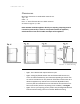
U N I Q U E 2 Chapter U G P - 2 2 Installation of Appliance For best performance at high ambient temperatures, there must be free air circulation over the cooling unit at the rear of the refrigerator. Ensure that there is a free air space above the refrigerator and that the flue (chimney) on top of the cabinet is not covered in any way. Do not place the refrigerator in a space where air circulation is restricted. Follow “clearance” instructions.
U N I Q U E U G P - 2 2 Clearances Minimum clearances to combustible materials are: Top – 10” Sides – 2” Rear – 1” with left hand side rear shield mounted as shown in Figures. 1, 2 & 3. Note: DO NOT install the appliance directly on carpeting. Carpeting must be removed or protected by a metal or wood panel beneath the appliance, which extends at least the full width and depth of the appliance.
U N I Q U E U G P - 2 2 Gas Connection Hook-up to the gas supply line: 3/8” SAE (UNF 5/8” - 18) male flare connection. A backup wrench must be used when tightening gas supply fitting. All completed connections should be checked for leaks with a non-corrosive leak detector and/or soap and water for a bubble check.
U N I Q U E 3 Chapter U G P - 2 2 General Operating Instructions Importance of Leveling a Refrigerator The refrigerator must be adjusted to a vertical position in both directions. In an absorption refrigeration system, ammonia is liquefied in the finned condenser coil at the top rear of the refrigerator.
U N I Q U E U G P - 2 2 Gas Operation “Start Up” Procedure – see Figure # 5 on next page for control panel 1. Locate the control panel below at the bottom front of fridge 2. Turn the gas shut off valve C to the ON position – to the left 3. Turn thermostat button B fully clockwise (Max), start to spark igniter button A before depressing the gas control button E, there may be a period of time required for air to escape from the gas line and flow up to burner.
U N I Q U E U G P - 2 2 Figure #5 Thermostat A thermostat controls the refrigerator cooling temperature; it can be adjusted by turning knob B to different settings to maintain the desired refrigerator temperature. Knob E also incorporates a safety device, which automatically shuts off the supply of gas if the flame goes out. The piezo electric igniter discharges sparks onto the burner when the button is pushed. 1.
U N I Q U E U G P - 2 2 How to Use the Refrigerator FOOD STORAGE COMPARTMENT The food storage compartment is completely closed and unventilated, which is necessary to maintain the required low temperature for food storage. The coldest areas in the refrigerator are under the cooling fins and at the bottom of the refrigerator. The warmer areas are on the upper door shelves. This should be considered when placing different types of food in the refrigerator.
U N I Q U E U G P - 2 2 FRIDGE SECTION Inside the refrigerator compartment, the defrost water runs from a collector channel to a drip tray/cup at the rear of the refrigerator where it normally evaporates. If heavy frost has built up on the cooling fins creating a lot of defrost water, beware your water reservior may overflow, we suggest you inspect reservoir before and after cycle.
U N I Q U E 4 Chapter U G P - 2 2 Maintiance & Service The user should be aware of service that must be done on a regular schedule to keep the refrigerator operating properly. Installation must be by a licensed gas fitter in accordance with local codes or in the absence of local national Fuel Gas Code, ANSI Z233.1 and in Canada B149.2 Propane Storage and Handling Code (latest edition). REFRIGERATOR REMOVAL Before working on the refrigerator, shut off the gas supply.
U N I Q U E U G P - 2 2 • Check all connectors in the complete refrigerator LP gas system for gas leaks. The LP gas supply must be turned on. Apply a non corrosive bubble solution to all LP connections. The appearance of bubbles indicates a leak and should be repaired immediately by a qualified serviceman. WARNING – DO NOT USE FLAME TO CHECK FOR GAS LEAKS Check burner flame for proper appearance. The flame should be light blue with no yellow at the tip. See figure #6 Fig. #6 Fig.
U N I Q U E U G P - 2 2 o o o o Remove the wire and flue baffle from the top of flue tube. Clean the flue from the top using a flue brush, be sure to cover the burner if remaining intact to eliminate dirt falling into burner. Replace the flue baffle. Clean burner tube with compressed air, check for fluff or spider webs. Before removing burner orifice, clean burner area of any soot, scale or dirt.
U N I Q U E U G P - 2 2 o If leak occurs, then allow ten minutes to dissipate from the burner area.
U N I Q U E 5 Chapter U G P - 2 2 TROUBLESHOOTING INSTRUCTIONS & SUGGESTED SPARE PARTS TO KEEP ON HAND REFRIGERATOR DOES NOT COOL, CHECK LIKELY CAUSES: 1. Burner orifice clogged. Clean. See section Maintenance & Service, CHAPTER 4, Item #2. Periodic Maintenance, Items 1-9. 2. Check to ensure refrigerator is level – (left to right and front to back). 3. Restriction on air flow across cooling unit. 4. Heavy frost build up on evaporator fins. Defrost. 5.
U N I Q U E U G P - 2 2 Spare Parts The following is a list of commonly used parts which are available: • Burner orifice • Burner • Electrode • Thermocouple • Safety valve & thermostat • Piezo igniter (push button) • Baffle Contact your dealer or an authorized service center for parts and repairs as needed. Quote Model & Serial # - See CSA rating/serial plate on inside left wall.
U N I Q U E 6 Chapter U G P - 2 2 Carbon Monoxide Monitor Instructions for Model UGP-22 OWNER’S MANUAL Model 9RV-SSO Carbon Monoxide Alarm for Appliance Safety Shutoff ATTENTION: PLEASE READ, FOLLOW AND SAVE! (See Additional Instruction Sheet for Safety Shutoff Connection) Dear New COSTAR 9RV-SSO Owner, Congratulations as you have taken steps to help ensure the health and safety of you and your family.
U N I Q U E U G P - 2 2 WARNING: Failure to replace this product by the “REPLACE BY DATE” printed on the alarm cover may result in death by Carbon Monoxide poisoning. Replace by date is six (6) years from date of manufacture. 1.0 WHAT YOU SHOULD KNOW ABOUT CO Carbon monoxide (CO) is an insidious poison. It is a colorless, odorless and tasteless gas. It is a cumulative poison.
U N I Q U E U G P - 2 2 Individuals with medical problems may consider using warning devices that provide audible and visual signals for carbon monoxide concentrations under 30 ppm. 2.0 WHAT YOU SHOULD DO IF THE ALARM SOUNDS WARNING: Activation of this device indicates the presence of carbon monoxide (CO) which can KILL YOU.
U N I Q U E U G P - 2 2 30 seconds); contact Unique Gas Products for troubleshooting and/or instructions to return the unit: 2.1 IMPORTANT CONSIDERATIONS: The COSTAR 9RV-SSO has been designed and is warranted to operate for six years. Never disconnect the battery to silence an alarm. The alarm will automatically sense when the level of CO in the air falls below the danger level. You should stay outside the residence, or unconditioned area and remain in fresh air until the alarm is silenced.
U N I Q U E U G P - 2 2 safely. – Know where to go to call the Fire Department or professional assistance from outside your residence. – Know where to go to call the emergency service provider and or a qualified service technician. 4.0 IMPORTANT: WHAT YOUR CO ALARM CAN AND CANNOT DO 4.1 This unit is designed to detect carbon monoxide (CO) and shutoff an appliance for safety only. 4.2 This CO alarm is designed for use within a single residential living unit.
U N I Q U E U G P - 2 2 WALL LOCATION: Mount the alarm at least 3 feet (usually 5 – 6 feet) from the floor. Figure 1: Recommended CO alarm wall mounting location is 5 to 6 feet from floor 5.3 LOCATIONS TO AVOID: Nuisance alarms are caused by placing units where they will not operate properly. To avoid nuisance alarms, do not place units: – Within 5 feet (1.5m) of any cooking appliance or furnace.
U N I Q U E U G P - 2 2 3 Simultaneous operation of several fuel burning appliances competing for limited internal air. 4 Vent pipe connections vibrating loose from clothes dryers, furnaces, refrigerators, or water heaters. 5 Obstructions in or unconventional vent pipe designs which can amplify the above situations. 6.0 5.4.2 Extended operation of un-vented fuel burning devices (range, oven, fireplace, etc.) 5.4.3 Temperature inversions, which can trap, exhaust gasses near the ground. 5.4.
U N I Q U E U G P - 2 2 Step B: Alarm Activation Step C: Removal and Installation Figure 2: Installation Instructions 6.3 To insure aesthetic alignment of the alarm with the hallway or wall, the UP arrow on the mounting plate must be vertical when wall mounting: (See Step A in Figure 2) 6.4 As described in Figure 2, attach the mounting plate on the wall. Use the screws and anchors provided to secure the mounting plate. 6.5 The battery is INSTALLED REVERSED FOR SHIPPING.
U N I Q U E U G P - 2 2 change the battery; this can be done easily with a long nose pliers. Using the long nose pliers pull the pin out of the hole, it is now possible to remove the alarm from the mounting plate. Figure 3: Tamper Resistant Locking Pin 6.8 This box contains two self-adhesive labels. You should write the telephone numbers of the emergency service provider and a qualified technician in the space provided on the labels.
U N I Q U E U G P - 2 2 8.2. To clean your alarm, remove it from the mounting bracket as outlined in Figure 2 Step D: Installation/Removal. IF TAMPER RESISTANT PIN HAS BEEN USED, REFER TO STEP 6.7 UNDER INSTALLATION INSTRUCTIONS FOR REMOVAL INSTRUCTIONS. (See Figure 3) 8.3 You can clean the interior of your alarm by using your vacuum cleaner hose and vacuuming through the openings around the perimeter of the alarm. 8.4 The outside can be wiped with a cloth. 8.
U N I Q U E U G P - 2 2 9.3 USE ONLY THE FOLLOWING 9 VOLT BATTERY FOR CO ALARM REPLACEMENT: Alkaline type: DURACELL: MN1604 WARNING USE ONLY THE BATTERY SPECIFIED. USE OF DIFFERENT BATTERIES MAY HAVE A DETRIMENTAL EFFECT ON THE CO ALARM. THE CONSTANT EXPOSURES TO HIGH OR LOW TEMPERATURES OR HIGH HUMIDITY MAY REDUCE BATTERY LIFE. CHECK THE BATTERY MANUFACTURERS SPECIFICATIONS FOR PROPER OPERATING CONDITIONS. Note: Most batteries are not rated below -20°C or above 54°C 10.
U N I Q U E 7 Chapter U G P - 2 2 Door Removal & Reversal Instructions NOTE: The direction in which your refrigerator doors open (door swing) can be reversed, from left to right or right to left, by moving the door hinges from one side to the other. A qualified person should perform reversing the door swing. Some earlier Stainless Steel models are not reversible, they had to be ordered as Left or Right hinged. 1. Remove toe grille and top hinge cover. 2.
U N I Q U E U G P - 2 2 9. Move freezer and refrigerator door stops to opposite side. Before starting screws, use an awl to puncture the foam. 10. Position refrigerator door onto bottom hinge pin and screw center hinge pin through center hinge into top of door. Close refrigerator door to help align hinge hole. 11. Tighten center hinge pin with adjustable wrench. 12. Remove cabinet and hinge hole plugs and move to opposite side. 13. Lower freezer door onto center hinge pin. 14. Close freezer door.
U N I Q U E U G P - 2 2 To Remove Fridge or Freezer Handle (Handles may be easier to reverse while doors are off.) 1. Remove two screws attaching handle to bottom of freezer door. 2. Lift off handle from dovetail screw. To Attach Fridge or Freezer Handle 1. 2. 3. 4. 5. To reinstall handle on opposite side, first remove small plug on side of door.
U N I Q U E 8 Chapter U G P - 2 2 Temperature Controls Note: Maximum setting is override; therefore the thermostat function is not operational at this setting. This setting is usually only required during very hot and humid days. COOL DOWN PERIOD To ensure safe food storage, allow the refrigerator to operate with the doors closed for at least 8 hours before loading it with food.
U N I Q U E U G P - 2 2 Looking Inside SHELF ADJUSTMENT Refrigerator shelves are easily adjusted to suit individual needs. Before adjusting the shelves, remove all food. Crispers & Deli Drawers The crispers, located under the bottom refrigerator shelf, are designed for storing fruits, vegetables, and other fresh produce. Wash items in clean water and remove excess water before placing them in the crispers. Items with strong odors or high moisture content should be wrapped before storing.
U N I Q U E U G P - 2 2 Food Storage Ideas FRESH FOOD STORAGE • • The fresh food compartment should be kept between 38° F and 40° F (3.3° C and 4.4° C) with an optimum temperature of 38° F (3.3°C). Avoid overcrowding the refrigerator shelves. This reduces the circulation of air around the food and results in uneven cooling. FRUITS AND VEGETABLES • Storage in the crisper drawers traps moisture to help preserve the fruit and vegetable quality for longer time periods.
U N I Q U E U G P - 2 2 LOADING THE FREEZER • • • Avoid adding too much warm food to the freezer at one time. This overloads the freezer, slows the rate of freezing, and can raise the temperature of frozen foods. Leave a space between the packages, so cold air can circulate freely, allowing food to freeze as quickly as possible. Avoid storing hard-to-freeze foods such as ice cream and orange juice on the freezer door shelves.
U N I Q U E 9 Chapter U G P - 2 2 Parts Diagram and List 35
U N I Q U E U G P - 2 2 36
U N I Q U E U G P - 2 2 37
U N I Q U E U G P - 2 2 Burner Train Assembly UGP-22 38
U N I Q U E U G P - 2 2 UNIQUE UGP-22 Fridge Item# PART# DESCRIPTION 1 UGP22-01 FREEZER DOOR GASKET - WHITE 1 UGP22-02 FREEZER DOOR GASKET – BLACK 1A UGP22-03 FRIDGE DOOR GASKET - WHITE 1A UGP22-04 FRIDGE DOOR GASKET - BLACK 2 UGP22-05 PLUG, WHITE 2 UGP22-06 PLUG, BLACK 3 UGP22-07 FREEZER DOOR - WHITE 3 UGP22-08 FREEZER DOOR - STAINLESS STEEL 3 UGP22-09 FREEZER DOOR – BLACK 4 UGP22-10 CAP, WHITE 4 UGP22-11 CAP, BLACK 5 UGP22-12 HANDLE, SCREW 6 UGP22-13 HANDLE, SCRE
U N I Q U E U G P - 2 2 Item# PART# DESCRIPTION 11 UGP22-25 FRIDGE DOOR - WHITE 11 UGP22-26 FRIDGE DOOR - STAINLESS STEEL 11 UGP22-27 FRIDGE DOOR – BLACK 12 UGP22-28 SCREW 13 UGP22-29 FRIDGE DOOR RACK – TOP & LOWER 14 UGP22-30 FRIDGE DOOR RACK – MIDDLE 15 UGP22-31 DAIRY COVER, (ALL MODELS) 16 UGP22-32 FREEZER DOOR RACKS 17 UGP22-33 SCREW FREEZER AND FRIDGE HANDLES 18 UGP22-34 TRIM SHELF REAR 19 UGP22-35 GLASS SHELF 20 UGP22-36 TRIM SHELF FRONT 21 UGP22-37 FRAME - S
U N I Q U E U G P - 2 2 Item# PART# DESCRIPTION 34 UGP22-51 HINGE COVER - BLACK 35 UGP22-52 TOP HINGE SCREWS 36 UGP22-53 TOP HINGE 37 UGP22-54 CORNER TRIM - WHITE 37 UGP22-55 CORNER TRIM - BLACK 38 UGP22-56 MIDDLE HINGE SHIM 39 UGP22-57 NYLON WASHER 40 UGP22-58 MIDDLE HINGE PIN 41 UGP22-59 MIDDLE HINGE - CHROME 41 UGP22-60 MIDDLE HINGE - BLACK 42 UGP22-61 MIDDLE HINGE SCREWS 43 UGP22-62 BOTTOM HINGE PIN 44 UGP22-63 BOTTOM HINGE - CHROME 44 UGP22-63 BOTTOM HINGE
U N I Q U E U G P - 2 2 Item# PART# DESCRIPTION 55 UGP18-52 BURNER TUBE 56 UGP18-53 ELECTRODE WITH WIRE 57 UGP18-54 ORIFICE 58 UGP18-50 THERMOCOUPLE 59 UGP1518-5 INLET GAS TUBE 60 UGP1518-4 OUTLET GAS TUBE 61 UGP18-56 PEIZO IGNITOR 62 UGP18-57 FLAME INDICATOR 63 UGP1518-9 SAFETY VALVE 64 UGP1518-2 KNOB, THERMOSTAT 65 UGP1518-1 ON/OFF VALVE 66 UGP1518-6 INLET FITTING 67 UGP1518-8 PIPE – ON/OFF VALVE TO THERMOSTAT CONTROL 68 UGP1518-7 THERMOSTAT CONTROL 69 UGPSP
U N I Q U E U G P - 2 2 UNIQUE UGP-22 5 YEAR LIMITED WARRANTY* Unique Gas Products Ltd. warrants that this UNIQUE refrigerator is free from defects in material and workmanship under normal usage and service under the following terms: 1. This Warranty is made only to the first purchaser (”original purchaser”) who acquires this refrigerator for his/her own use and will be honored by Unique Gas Products Ltd. and by the Seller. 2.
U N I Q U E U G P - 2 2 LIMITED WARRANTY COSTAR Model 9RV-SSO UNIQUE GAS PRODUCTS LTD offers you this limited warranty on your new carbon monoxide alarm, including all of its component parts except the battery. This limited warranty extends solely to the original end-user purchaser of this product, provided your purchase was made from an authorized vendor. Transfer or resale of this product will automatically terminate warranty coverage. UNIQUE GAS PRODUCTS LTD.