CLASSIC RETRO BY UNIQUE 36” RANGE HOOD MODEL NUMBERS: UGP-36CR RH W, UGP-36CR RH T, UGP-36CR RH LG, UGP-36CR RH B OWNER’S GUIDE serial number: OCT22V1 4002621
TABLE OF CONTENTS SAFETY NOTICE 03 PRE INSTALLATION 06 NECESSARY TOOLS 08 PARTS INCLUDED 09 PARTS LIST 09 INSTALLATION PROCEDURE 10 OPERATING INSTRUCTIONS 15 TROUBLESHOOTING 15 MAINTENANCE 16 TECHNICAL SPECIFICATIONS 17 WIRING DIAGRAM 17 WARRANTY 18 APPLIANCE INFORMATION 20 PRODUCT REGISTRATION 20 CONTACT US 2 21
SAFETY NOTICES Approved for residential type units for residential use only read these instructions and be safe. Please read these instructions completely before starting. The installation of the appliance must respect all codes. Important: Save these instruction so that you can provide the electrical inspector in your area. Safety Warning: Turn off the circuit in the electrical panel and lock front panel to connect the cord of this unit.
SAFETY NOTICES To reduce the risk of fire and to properly exhaust air, be sure that the pipe is leading outside, do not exhaust air into the space between the walls, ceilings, attics, crawl spaces or garages. WARNING — GROUNDING INSTRUCTIONS This device must be grounded. In the event of an electrical short circuit, grounding reduces the risk of electric shock by providing an escape wire for the electric current. This appliance is equipped with a cord with a grounding wire with a grounding plug.
SAFETY NOTICES WARNING — TO AVOID INJURING SOMEONE IN A GREASE FIRE, FOLLOW THE FOLLOWING: 1. SMOTHER FLAMES with a lid to the dimensions of the cooking hobs, a cookie sheet or other metal tray, then turn off the gas or power supply of the stove. BE CAREFUL NOT TO BURN YOURSELF. If the flames do not go out immediately, LEAVE AND CALL THE FIRE DEPARTMENT. 2. NEVER PICK UP A FLAMING PAN. You could be hurt. 3.
PRE INSTALLATION CAUTION Due to the weight and size of these vent hoods and to reduce the risk of personal injury or damage to the product, TWO, TO THREE PEOPLE ARE REQUIRED FOR PROPER INSTALLATION. • Please read the instructions carefully. Unpack the range hood and check that all functions are working before installing. • Ensure that the voltage (V) and the frequency (Hz) indicated on the sticker match the voltage and frequency at the installation site.
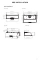
PRE INSTALLATION MEASUREMENTS Front View Top View 45.8 mm (1.8”) 905.0 mm (35.6”) 905.0 mm (35.6”) 900.0 mm (35.4”) 873.0 mm (34.4”) 220.0 mm (8.7”) 558.8 mm (22.0”) 254.3 mm (10.0”) 770.0 mm (30.3”) 900.0 mm (35.4”) 3/4 View Side View 905.0 mm (35.6”) 900.0 mm (35.4”) 305.0 mm (12.0”) 770.0 mm (30.3”) 254.3 mm (10.0”) (12 254.3 mm (10.0”) ) .0” m 5m 30 900.0 mm (35.4”) ) .0” 8.8 mm (22 558.8 mm (22.
PRE INSTALLATION DUCT PLANNING • The ventilation hood is equipped for 8” round ducts. This hood can be ventilated vertically through the top cabinet or ceiling. A duct transition piece is provided for vertical exhaust. You can use elbows (sold separately) to ventilate horizontally through the rear wall. • Determine the exact position of the hood. • Plan the route to vent the ventilation duct to the outside. • Use the shortest and straightest path possible.
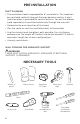
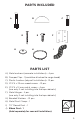
PARTS INCLUDED A B D G C E H F I PARTS LIST A) Metal anchors (concrete installations) - 4 pcs B) Damper Flap - 1 (could be attached to range hood) C) Plastic Anchors (drywall installations)- 10 pcs D) ST4*4 x 35 mm wood screws - 10 pcs E) ST4*4 x 12 mm metal screws - 4 pcs (use only if not installing into the top cabinets) F) Metal Hinges - 2 pcs (use only if not installing into the top cabinets) G) Beveled Washers - 10 pcs H) Metal Duct Clamp - 1 I) J 7.
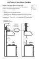
INSTALLATION PROCEDURES Caution: The range hood has sharp edges Please wear protective work gloves to remove parts, installation, cleaning and servicing. Step 1: • Connect the Duct into the Damper. • Secure the Duct around the Damper with the Duct Clamp. Important: For best results, the mounting height of range hood should be 65 - 75 cm (24” - 36”) above the top of the range. STEEL ELBOW DUCT RECOMMENDED FOR WALL MOUNTED INSTALLATION SECURE DUCT AROUND DAMPER WITH DUCT CLAMP (INCLUDED) MIN. 24” MAX.
INSTALLATION PROCEDURES MIN. 24” MAX. 36” CEILING HEIGHT 36” Step 2: Caution: When installing the hood, the height should not be too high or too low. Before the installation, please inspect the maximum height of your ceiling and bonnet. Too high, will affect the efficiency of the hood; too low, stove temperature will damage some parts of the hood.
INSTALLATION PROCEDURE Top and rear mount installation (USE HINGES ONLY IF NOT INSTALLING UPPER SCREWS INTO THE TOP CABINETS) Due to the weight of the unit, it is recommended to mount the hood at the bottom of the upper cabinet and then fix it to the wall to avoid gaps. 1. Use the installation template cut-outs to mark the necessary holes on the back and top of the hood with a pencil or marker. 2 Remove the template after marking 3.
INSTALLATION PROCEDURE TIGHTEN TOP FIRST TIGHTEN TO WALL SECOND THESE STEPS REQUIRE LIFTING AND HANGING AT THE SAME TIME - USE TWO/THREE PEOPLE 6. Locate the top (cabinet) holes and line up hood holes, while also lining up to holes with the protruding wall screws. 7. Fasten the hood to the bottom of the cabinet by tightening screws with a drill or screwdriver. 8. Tighten the screws to fix the hood to the wall once it is fixed to the cabinet. 9.
INSTALLATION PROCEDURE Metal Filter Installation 1. Install the Drip Tray inside the bottom rear of the range hood. (Fig 1) 2. Install the filters by inserting at an angle towards the rear of the range hood. (Fig 2) 3. Push the filter up and insert front of filter into front recess. (Fig 3) 4. Slightly lower the filter then slide back until it is in proper position.
OPERATING INSTRUCTIONS Touch Controls F1 Function Buttons: OFF F1 LOW SPEED F2 MEDIUM SPEED F3 HIGH SPEED F4 LED LIGHT F5 F2 F3 F4 F5 Fan Buttons: Power on by pressing any button of F2/F3/F4, fan starts and F5 light automatically but does not blink. TROUBLESHOOTING PROBLEM CAUSE SOLUTION After Installation, motor and lights are not working. The power is not on Make sure the circuit breaker and the unit’s power is ON.
MAINTENANCE CAUTION: NEVER PUT YOUR HANDS INSIDE THE RANGE HOOD WHILE IT IS IN OPERATION. CLEANING For best performance, clean the range hood regularly. 1. Use only mild soap or cleaning solutions to clean the exterior surface of the range hood. Use a soft cloth to dry the surface. 2. Stainless Steel Filters: For daily cleaning, use warm soapy water and a soft cloth. Pat dry and finish with a damp microfiber cloth. The filters can also be cleaned in the dishwasher. 3. Clean the hood assembly every 6 months.
TECHNICAL SPECIFICATIONS MODEL UGP-36CR RH SIZE 36” (91.44 cm) RATED POWER 700 CFM CONTROLS 3 speed power control NOISE LEVEL Below 65 dbA LIGHTS 1W LED Lamps x 2 CLEANING Dishwasher safe stainless steel baffle filters DIMENSIONS 10” H x 35.
CLASSIC RETRO BY UNIQUE 36” RANGE HOOD 1 YEAR LIMITED WARRANTY Unique Appliances Ltd. (hereafter “Unique”) warrants that this UNIQUE range hood is free from manufacturer’s defects in material and workmanship under normal usage and service under the following terms. Parts Warranty This appliance has been designed for domestic household use.
Removal or disfigurement of the rating plate will void the warranty. The purchaser will be responsible for any expenses involved in making the range hood readily accessible for servicing. The purchaser will be responsible for any extra charges where the installation is in a remote location such as un-assumed roads, islands, areas known as cottage country, more than 20 Km outside a Metropolitan area, or where a technician is not available. Freight damage is not covered by this warranty.
APPLIANCE INFORMATION (manual copy - keep with your records) Please record the following information for future reference: Model: Serial Number: Purchased From: Date Purchased: RATING LABEL Model No.: UGP-36CR RH Serial No.
CONTACT US For general information or questions related to the operation, safety or the purchase of your range hood, please contact our customer service department: Email info@UniqueAppliances.com Toll-free 1-877-427-2266 or 1-905-827-6154 available during regular business hours, 8:30 am to 4:30 pm, EST Website www.UniqueAppliances.com Please visit our website for more quality Unique products: www.UniqueAppliances.
© 2022 Unique Appliances Ltd., 2245 Wyecroft Road, Oakville, Ontario, Canada, L6L 5L7 www.uniqueappliances.