
Installation Instructions

8
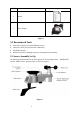
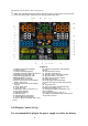
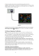
ThedisplayconsolelayoutisshowninFigure10
Note: The following illustration shows the full segment LCD display for description
purposes only and will not appear like this during normal operation.
Figure 10
1
.
O
ut
d
oo
r
temperature
di
sp
l
ay
2. WIFI network
3. Outdoor humidity display
4. Outdoor humidity HI/LO alarm icon
5. Min/Max reset for 24h icon
6. Rainfall display(RATE, 24h,
WEEK,MONTH, TOTAL)
7. Rainfall units of measure
8. Indoor temperature and humidity
HI/LO alarm icon
9. Indoor temperature and humidity
display
10. Time alarm icon
11. Time and date
12. Humidity units of measure (%)
13. UV Index display
14. Sunshine intensity
15. MOON phase
16. Sunlight units of measure
17. Sensor Heat index display
18. Sensor Heat index(heat index; dew
point)
19
.
O
ut
d
oo
r
temperature an
d
h
um
idi
ty
display
20. Scroll mode indicator
21. Channel 1-8 indicator
22. Pressure (REL and ABS) display
23. Pressure units of measure
24. Wind speed average display
25.Wind gust display
26.Wind speed units of measure
27.Wind chill and feels like HI/Lo alarm
icon
28. Wind direction
29. OUT dew point and AT(Apparent
Temperature) display icon
30. Integrated outdoor transmitter Low
power indicator
31.Temperature units (°F or °C)
32.Outdoor temperature HI/LO alarm icon
33.Weather forecast
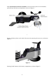
3.4.2Display Console Set Up
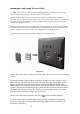
It is recommended to plug in the power supply to reduce the battery