
Unit installation


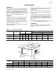


TABLE OF CONTENTS
General ................................................................................ 1
Renewal Parts...................................................................... 1
Inspection............................................................................. 1
INSTALLATION
Limitations............................................................................ 3
Location................................................................................ 3
Clearances........................................................................... 3
Rigging and Handling .......................................................... 4
Vertical / Horizontal Installation............................................ 4
Duct Connections................................................................. 4
Refrigerant Mains................................................................. 5
Drain Connection................................................................. 6
Supply Air Blower Adjustment ............................................. 6
Power and Control Wiring .................................................. 11
MAINTENANCE
Filters ................................................................................. 12
Evaporator Coil .................................................................. 12
Drain Pan ........................................................................... 12
Lubrication ......................................................................... 12
Belts ................................................................................... 12
TABLES
No. Description Page
1 Unit Application Data.................................. 3
2 Physical Data.............................................. 5
3 Blower Motor Pulley Adjustment ................ 7
4 Blower Performance ................................... 8
5 Accessory Static Resistance...................... 8
6 Blower Motor and Drive Data ..................... 8
7 Electrical Data ............................................ 11
FIGURES
No. Description Page
1 Unit Suspension Mounting ......................... 3
2 Vertical & Horizontal Application ................ 4
3 Supply Air Duct Connection ....................... 4
4 Electric Heater Accessory.......................... 5
5 Supply Air Plenum Accessory.................... 5
6 Base Accessory.......................................... 5
7 Return Air Grille Accessory........................ 5
8 Recommended Drain Piping ...................... 6
9 Motor Mounting Assembly.......................... 7
10 Hole Locations for Pressure Readings....... 7
11 Pressure Drop vs. Supply Air CFM ............ 7
12 Unit Dimensions & Clearances (5 tons) ..... 9
13 Unit Dimensions & Clearances ................. 10
(7-1/2 & 10Tons)
14 Typical Field Wiring..................................... 11
K 4
E
U 090
A
3 3
PRODUCT CATEGORY
K - S p lit-S y s te m E v a p . B lo w e r
W ith M o to r a n d D riv e
PRODUCT GENERATION
2 - 2nd G eneration
3 - 3rd G eneration
4 - 4th G eneration
PR O DUCT IDEN TIFIER
E U - E v a p o ra to r B lo w e r
NOM INAL
COOLING CAPACITY
FAC TO RY
INSTALLED HEAT
A - N ot Applicable
VOLTAG E CO DE
060 - 5 TO N
090 - 7-1/2 TO N
120 - 10 TO N
0 6 - 2 0 8 /2 3 0 -1 -6 0
3 3 - 2 0 8 /2 3 0 /4 6 0 -3 -6 0
NOMENCLATURE
550.23-N2Y
2 Unitary Products Group