EZ Trak Installation and Operations Manual Unitec www.StartwithUnitec.
E Z T R A K EZ TRAK INSTALLATION AND OPERATIONS MANUAL This manual provides comprehensive installation, setup, and operational procedures for the EZ Trak Fleet Terminal. If further assistance is needed, please contact the distributor from which the product was purchased. When calling for assistance, you must have the following information available: EZ Trak Serial Number: Distributor Name: C O P Y R I G H T © 2011 Unitec, Incorporated. All rights reserved.
E Z T R A K Table of Contents 1 Introduction.....................................................................................................................................1 1.1 Electrical Planning......................................................................................................................1 1.1.1 Electrical Requirements of the EZ Trak........................................................................................1 1.2 Mechanical Planning ............................
E Z T R A K Index of Figures Figure 1. Conduits with Ethernet Cable Layout ............................................................................... 2 Figure 2. EZ Trak Base Placement.................................................................................................. 3 Figure 3. EZ Trak Terminal Base..................................................................................................... 5 Figure 4. EZ Trak Terminal Base Dimensions ...........................................
E Z T R A K 1 Introduction The EZ Trak fleet terminal is a drive-up entry system developed specifically for the automobile dealer market. EZ Trak cards and codes allow the dealer to track all wash use by driver and department. EZ Trak can be used to track car wash use by rental companies, neighboring dealerships and businesses. EZ Trak is designed to integrate with the dealer’s local computer network. It requires 24 Volt AC or DC power, Intranet (Ethernet) connection, and a web browser. 1.
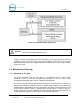
E Z T R A K Figure 1. Conduits with Ethernet Cable Layout DO NOT RUN CABLE OUTSIDE OF A CONDUIT! Important: Follow all local and National Electric Codes. Finally, it should be understood that the EZ Trak terminal is to be powered by wires of at least 18 AWG, or larger. Failure to adhere to this recommendation could result in a fire or injury. When installing the conduit, it is suggested that it be a minimum of ¾” in size, and be made of metal versus PVC. 1.2 Mechanical Planning 1.2.
E Z T R A K 1.2.2 Mechanical Requirements It is strongly recommended that the unit be mounted on a concrete slab. The concrete should be a minimum of 5” inches thick, 21” inches wide, and 13” inches long (Refer to Figure 2). The dimensions and positioning of the mounting holes for the mounting plate will be covered in the “Mechanical Installation” section of this manual. The front edge of the unit should be 18 inches from the driver’s side tire centerline.
E Z T R A K 2 Installation 2.1 Mechanical Installation Tools The following tools are recommended for the typical mechanical installation of this EZ Trak unit: 6” inch or longer ratchet extension (for optional straight base) ¾” inch deep well socket and socket wrench Small, thin blade, flat-tip screwdriver Hammer drill ½” Concrete hammer drill bit Hammer Dual-plane Level 50’ foot tape measure 2.
E Z T R A K 2.3 Installation of the Terminal The EZ Trak terminal is bolted onto the concrete base. Perform the following steps: 1. Center the EZ Trak terminal on the concrete base. Please note that the bolt holes are inside the terminal, as shown in the picture the below. Figure 3. EZ Trak Terminal Base 2. Mark the 4 holes that you intend to drill in order to mount the EZ Trak. Mark the holes with a marker as the terminal is sitting on top of the concrete.
E Z T R A K Figure 4. EZ Trak Terminal Base Dimensions Warning: DO NOT BEGIN MOUNTING OF THE TERMINAL UNTIL ALL WIRES & CABLES HAVE BEEN PULLED THROUGH THE CONDUITS! 3. Using the hammer drill, and the ½” inch concrete drill bit, drill the four holes. Ensure that the holes are drilled deep enough to insert the anchor bolts. A good depth is approximately 2”-2½” inches from the surface of the concrete. 4.
E Z T R A K 5. When all anchor bolts have been set, place one nut onto each of them, and use the ratchet and socket to tighten it, until as many of the threads from the bolts as possible are showing. There should also be sufficient threads on the anchor bolts left to secure the plate in place with the remaining 4 nuts. If this is not the case, the holes in the concrete were drilled too deep, and the installer should use smaller, or no leveling nuts. 6. Securely fasten the 4 nuts with the socket wrench.
E Z T R A K 2.4 Electrical Installation 2.4.1 Wiring for the Interface Board Figure 6. Interface Board Connections Notes on installation: 1. The carwash PLC activation voltage is applied to the program relay output in order to activate the carwash. 2. The Wash-In-Use signal cannot exceed 110 VAC. 3. The heater is active when the red light (D2) is on. 2.4.2 Wash Outputs 1.
E Z T R A K panel. You will be making connection to the interface board connector J7, pins 3 and 4. 2. Use the screwdriver to open and/or secure the manufacturer wash wires to each of the appropriate Unitec relay locations in accordance with the following table: Table 1. Wash Program Relays Signal: EZ Trak Interface Board Wash Program Relay Output J7, Pin 3 Wash Program Relay Input J7, Pin 4 2.4.
E Z T R A K 3 System Configuration Setup and configuration of the EZ Trak is completed via the Internet using a laptop or desktop computer with Internet access. The network parameters for the EZ Trak terminal are configured at the terminal itself. The Fleet Terminal Ethernet interface comes shipped pre-configured with the following settings: • IP Address: 192.168.0.108 • Netmask: 255.255.255.0 • Gateway: 192.168.0.1 • DHCP: Off To confirm these settings, enter the keypad code “123456789#”.
E Z T R A K 3.1 Quick Setup To access the EZ Trak main menu, connect the Ethernet port to you PC network hub or router then enter http://192.168.0.108 (or the IP address you programmed) into your web browser address. 1. Login to the Main Menu using the Master login User Name: NADA and Password: UE. 2. Login to the Password Administration Menu using the Master login. Enter all screen user names and passwords. Check the box and click Submit. 3. Login to the Admin Menu.
E Z T R A K 4 Operations The EZ Track Fleet Terminal main menu includes the following functions, as defined below: • Account Reports – provides a detailed report of account usage for every account or a summary of usage for each department. • List All Accounts – provides a detailed list of all accounts plus a link to setup accounts.
E Z T R A K 4.1 Account Reports Figure 7. Sample Account Report Screen The Account Reports screen displays the information for the last counter reset, and washes used for all accounts, departments, one use codes and summarizes the totals. One use codes are included in the summary of totals of washes used. Invalid codes and cards are displayed at the bottom of the screen. To refresh the report, click the Submit button.
E Z T R A K 4.2 List All Accounts Figure 8. Sample List All Accounts Screen The List All Accounts screen displays the account name, the department, the remaining washes, the card code, the keypad code and the key/card status for each account. You may also delete an account from this page by selecting the Delete Account box then clicking Submit.
E Z T R A K 4.3 Setup/Change Accounts Figure 9. Setup/Change Account Screen The Setup/Change Account function allows you to add, change and delete accounts from the EZ Trak system. To add or change an account: 1. Click and select the number of accounts you wish to add under the Add Accounts drop-down menu. Accounts are added below that row, allowing you to arrange accounts in any order. 2. Enter an Account Name (max 20 characters). 3. Enter the Department Name (max 10 characters).
E Z T R A K 9. To delete an account, select the Delete Account box next to the account you wish to delete then click Submit. 4.4 One Use Codes Figure 10. Sample One Use Codes Screen The One Use Codes function provides 50 keypad codes that will activate the wash once. These codes are valid until used or until a new set of codes is generated. When entering a keypad code at the terminal, the code is followed by the “#” key which acts as the “enter” key.
E Z T R A K 4.5 Transaction Log Figure 11. Sample Transaction Log Screen The Transaction Log provides a detailed list of the last 100 transactions at the Fleet Terminal, including the account name, department, washes left on the account, date time and day of the week the account was used, any invalid codes and cards, and system information, such as power cycling and memory resets.
E Z T R A K 4.6 Administration Figure 12.
E Z T R A K The Administration screen allows you to perform several administrative functions for the EZ Trak system, including resetting system counters, backing up and restoring data, changing the dealer name, and resetting the system clock. 4.6.1 Wash Account Counter Administration The Wash Account Counter Administration function allows you to reset system counters by day, week month, quarter or year or any other increment you chose.
E Z T R A K 4.6.4 Reset System Clock The Reset System Clock function allows you to set the local time on the EZ Trak system world-wide. Enter the date, time and day of the week and click the Submit button. The system time does not automatically update, so it will need to be manually updated for Daylight SavingsTime. 4.7 Password Administration Figure 13. Password Administration Screen The Password Administration screen allows you to manage access to the EZ Trak system.
E Z T R A K during that session. If you terminate the browser and restart, the user name/password will be required again. A master username and password plus default usernames and passwords for each web page are provided in the system. You may change any or all of user names and passwords (max 15 characters each) on the Password Administration page. Once the values are changed, you must click Submit to save the changes.
E Z T R A K Document Number: Document Title: EZT1001 EZ Trak Installation and Operations Manual 22
E Z T R A K Appendix A: 120 VAC Power Supply (Optional) The 120 VAC power supply is supplied as an option for those who wish to power their EZ Trak system from a junction box. The power supply is attached to the DIN rail on the back wall of the unit then connected to the junction box and power distribution board. 1. Connect the power supply to the DIN rail by centering the slot on the back of the power supply on the DIN rail then push down firmly.
E Z T R A K Appendix B: Connecting EZTrak to Network Hub or Switch A standard Cat5 cable is used to connect the EZTrak to a network hub or switch using standard “straight-through” wiring in the connectors. A straight through cable has both ends with the same pin color code. These cables may be readily purchased from Radio Shack, but you may also wire the connector yourself.
E Z T R A K Appendix C: Configuring the EZ Trak on the LAN If your site does not have an existing Internet connection, you may configure the EZ Trak with a laptop, a cross-over cable, and a CAT5 coupler. A cross-over cable is a Cat5 cable that has the wires reversed at opposite ends of the connector. These cables are readily available at Radio Shack, but you may also wire the connectors yourself.
E Z T R A K 5. Select Internet Protocol (TCP/IP).
E Z T R A K 6. Click Properties. 7. Select “Use the Following IP Address” then fill in the following network information: IP Address: 192.168.0.110 Subnet Mask: 255.255.255.0 Default Gateway: 192.168.0.1 8. Leave the DNS information blank. 9. Click OK. 10. Plug the CAT5 cable from the pay node in the EZ Trak into the coupler. Plug one end of the cross-over cable into the coupler and the other end into your laptop. 11.