Portal TI Installation Manual Unitec 443-561-1200 • www.StartwithUnitec.
PORTAL TI PORTAL TI INSTALLATION MANUAL Revision C This manual provides comprehensive installation procedures for the Portal TI. It includes the process of site planning, site preparation, the mechanical installation of the Portal TI and the electrical wiring of the unit. If further assistance is needed, please contact the distributor from which the Portal TI was purchased.
PORTAL TI Table of Contents 1 Site Planning and Preparation ......................................................................................................1 1.1 General ..................................................................................................................................1 1.2 Mounting Options...................................................................................................................1 1.3 Positioning the Portal..................................
PORTAL TI 3.9 4 Camera Connection.............................................................................................................30 3.10 Gate Wiring .......................................................................................................................30 3.11 Connecting the Reach Free ID Option..............................................................................30 System Test.........................................................................................
PORTAL TI 1 Site Planning and Preparation 1.1 General This chapter provides guidelines for planning the Portal installation and preparing the site. Site preparation includes: • Determining how and where the Portal will be mounted • Installing conduit runs and required wiring Note: These instructions serve as general guidelines only. If your wash manufacturer’s installation requirements differ from these guidelines, always meet the wash manufacturer’s requirements first.
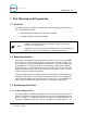
PORTAL TI achieve this dimension, the Portal base frame should be located 26 in. from the conveyor centerline as shown in Figure 1. Figure 1. Portal Installation at the Wash Entrance For curb mount applications, the front surface of the Portal should be even with the edge of the curb. To achieve this dimension, the base frame should be installed so its leading edge is 8 in. from the edge of the curb as shown in Figure 2. Figure 2.
PORTAL TI 1.3.2 Express Wash Applications Express Exterior sites should be designed to provide 9 ft. wide traffic lanes at the Portals. The traffic control (or barrier) gate should be located approximately 10 ft. from the center of the Portal and an underground vehicle detection loop is required under the gate arm. In some cases, it may be desirable to install a 2nd loop between the gate and tunnel entrance (referred to as the merge loop) to properly manage the vehicle queue.
PORTAL TI 1.4 Electrical Preparation 1.4.1 Conduit Installation A typical installation will require 3 conduit runs for, power, data and wash control lines. DO NOT run data wires in the AC Power or Wash Control conduits. Additional conduit runs may be needed when a gate or the Portal RFID option are to be used. Conduit size should be at least ¾ in, a larger conduit may be required depending on the quantity and gauge of wires to be installed.
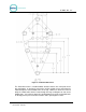
PORTAL TI Figure 5. Portal Base Dimensions The Portal base frame is a welded tubular structure that has the same plate on the top and bottom. Its designed so that wires and/or conduit can be routed into the Portal through the round conduit holes on the top. However, it will be far easier to bring the conduit stubs into the frame through the large rectangular cut outs on the bottom plate.
PORTAL TI 1.4.2 Power Requirements The Portal requires 120 VAC, 8 Amps service. In applications where barrier gates are to be used, each gate requires 120 VAC, 5 Amps service. The Portal and Gate must be powered from separate circuits. Note: Ensure the protective earth ground wires do not carry any motor return current. Only the neutral wire should carry return current. Follow local electrical code when wiring the Portal TI. 1.4.
PORTAL TI 2 Mechanical Installation 2.1 Hardware Required Prior to beginning the installation, take the time to verify that all the following required parts are present and accounted for.
PORTAL TI The following items are required only when installing the Portal TI into an existing concrete slab: • Hammer drill • 2.5” Concrete hammer drill bit 2.3 Base Installation Note: Pull all wires through conduits before mounting the base. See Electrical Planning for wiring requirements. When installing the Portal TI frame, it is recommended that the concrete pad be undercut, as illustrated in the figure below. This type of installation provides greater security.
PORTAL TI When installing the frame in pre-existing concrete, set the frame in the desired location and mark the location of each leg of the frame. Drill 2 ½ in. diameter by 8 in. deep (minimum) holes in the concrete for the frame legs. Fill the holes with concrete anchoring cement (such as Quickrete #1245-20) and insert the base legs. Ensure the frame is level and place the plastic base cover over the frame after the anchoring cement has set.
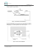
PORTAL TI Figure 7. Bricked-In Mounting Options 2.4.2 Positioning the Portal The adapter plate should be located so its front edge is recessed 4.50” from the front face of the brick structure (as shown in Figure 8). The adapter plate has (2) sets of mounting holes. One set is used to install the Portal so its front door will be flush with the brick. The other set is used to recess the door within the brick. These (2) mounting options and hole patterns are illustrated in Figure 9 and Figure 10..
PORTAL TI Figure 8.
PORTAL TI Figure 9.
PORTAL TI Figure 10. Portal Mounting for Bricked-In Installation 2.4.3 Brick-in Guidelines 2.4.3.1 Using the Adapter Plate The recommended procedure when mounting the Adaptor Plate directly to the brick structure is as follows: 1. Build the brick enclosure up to 36” high (8 rows of bricks) from the pavement. 2. Fill the enclosure with concrete. 3. Sink the Adaptor Plate with Mounting Bolts into the wet concrete. Position the Adaptor Plate 4 ½” back from the front edge of the brick.
PORTAL TI Figure 11. Portal Brick-In with Adaptor Plate 2.4.3.2 Using the Curb Height Frame Follow the base installation instructions in section 2.3 to set the base frame in the concrete. The adapter plate attaches to the (3) studs on top of the frame with ½” nuts and washers. Position the frame so the front of the adapter plate will be recessed 4.5” from the front face of the brick (as shown in Figure 12).
PORTAL TI Figure 12.
PORTAL TI [ T H I S P A G E Portal Installation Manual Rev C Document #: PTL1001 I N T E N T I O N A L L Y L E F T B L A N K ] 16
3 Electrical Installation 3.1 Hardware Required Unitec does not provide connectors for terminating the field-installed wires. These wires will vary by application but connectors that may be required include: • RJ-45 Modular Plugs (for terminating the CAT-5 network cable). • RJ-11 modular plugs (for terminating the telephone cable) • BNC Connectors (for terminating coaxial cable for the camera options) 3.
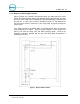
PORTAL TI Figure 13. Portal Interior 3.4 Connecting Power The Portal TI uses an IEC-320-C13 male power inlet to supply the unit with power. This inlet can be found on the back wall on the right-hand side of the Portal TI case. 1. Locate main power wires. There will be three 16 AWG (or greater) environmentally rated black, white, and green colored wires. 2. Route the main power wires to the Portal’s input power connector and remove excess wire length, leaving sufficient length to reach the AC power inlet.
PORTAL TI Figure 14. Inside the AC Connector 5. Remove the screw holding the stabilizer plate in place and set both aside until after you have finished securing the wires. 6. Thread the power wires through the strain relief. 7. Remove the white stabilizer plate. 8. Secure the Line (Black), Neutral (White) and Ground (Green) wires to the appropriate terminal screws. (See Figure 23). Re-tighten the screws to hold the wires in place. Figure 15. Line - Neutral - Ground Connections 9.
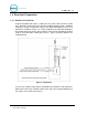
PORTAL TI 3.5 Network Connection The Cat 5 cable will need to be terminated at each end with an RJ-45 modular plug. This termination should be performed by a technician who is experienced in assembling network cables as a slight misalignment in the wire termination can cause communications problems. For reference, provides guidelines for terminating a network cable with a modular RJ-45 plug. The Network (Ethernet) port is located at the bottom edge of the carrier board as shown in Figure 16.
PORTAL TI 3.6 Telephone Cable A telephone cable is required if the Portal is equipped with the “Datatran” dial-up credit option. Each end of the cable should be terminated with RJ - 11 modular phone plug as follows: 1. Grasp the telephone cable and measure a length sufficient to route the cable to the Dataran. (Note: the Datatran is typically shipped after the Portal for installation on site. Refer to Appendix B for associated installation instructions and location of the phone line connection. 2.
PORTAL TI Figure 18. Telephone Line Connection (for Data Modem) 3.7 Wash Control Wiring 3.7.1 Overview In applications where the Portal will communicate with the Wash Controller, the wash control wires will need to be connected to the Wash I/O Board. Most wash manufacturers use a five-wire system to provide the arming signals for the selected wash packages. One common line and four arming input wires are fed from the wash’s PLC to the Wash I/O board.
PORTAL TI Each wash manufacturer has its own specific color code system and wash relay pinouts; therefore, it is important to review the appropriate wash documentation prior to beginning this portion of the installation. 3.7.2 Wiring the Wash Relay Interface To wire the wash relays, connect the wires that come from the PLC to the appropriate pin numbers in the phoenix connector using the following procedures: Note: 3.7.2.
PORTAL TI Figure 19. Wash I/O Board Connectors 4. Remove the Phoenix connector from the socket. 5. Turn the connector so that the wire inputs are facing up as shown below. Figure 20. 10-Pin Phoenix Connector Note: “Wash Output #”refers to the number associated with the arming wires. Refer to the wash manufacturer documentation for more information.
PORTAL TI 6. Referring to the figure above, connect the wash relay arming wires, the wash relay common wire, and any spare option relay wires to the appropriate pins, as indicated in the following table. Use the screwdriver to open and/or secure the manufacturer wash wires to each of the Unitec relay locations.
PORTAL TI • You will need a thin tipped, flat head screwdriver to open and tighten the relay connections of the Phoenix connector. • Review the wash manufacturer’s documentation to determine the color codes for the wiring of the wash pin-outs for your wash equipment before beginning this installation. • Phoenix connectors are shipped already inserted in the appropriate sockets on the Wash I/O board. 1.
PORTAL TI 3.8 Intercom Systems 3.8.1 Overview The use of an intercom system allows two-way communications between customers at the Portal and staff elsewhere on site. A customer activates the Portal’s intercom output by pressing the help button. Without an intercom, the intercom output can be used to activate a bell, light or other device to alert an attendant that help is needed. The intercom wires connect to the Display IO board on the back of the main door.
PORTAL TI Figure 22. Intercom Component Locations on the Display IO Board 3.8.4 Connection Overview Call Function: A view of the diagram below shows J34 and J35. The unit will initiate a call function by closing the contacts on RL5. By default, J34-Pin 1 (H1) and J34-Pin 2 (H2) will always reflect the contact closure of RL5. This is the default for the fourwire mode when both the call function and audio are completely separated. More detailed instructions on this follow.
PORTAL TI Figure 23. Four-Wire Intercom Configuration 3 Wire Intercom Configuration: This mode requires two conductors for audio and one additional conductor for the call function. This mode uses a common ground for both audio and the call function (SP-). Jumper pins 3&4 of J35 and connect H1, SP+ and SP- as shown below. Figure 24. Three-Wire Intercom Configuration 2 Wire Intercom Configuration: This type of intercom system has both the Call Function and audio sharing the two conductors.
PORTAL TI 3.9 Camera Connection The (optional) surveillance camera is attached to the front door of the Portal. The camera is intended for use with a DVR or similar monitoring device installed at the site. The coaxial cable routed to the camera is used to connect it to the monitoring device. The coax cable will need to be terminated with a BNC connector similar to the one shown in Figure 26. Figure 26. BNC Male Plug for Camera Connection 3.
4 System Test Once the installation is complete, a thorough test should be performed to ensure all Portal functions are operational. This test should verify: • Functionality of hardware devices (through diagnostic tests in maintenance mode). • Washes and added services are properly configured and wash outputs are properly wired. • The wash fault (out of service) signal places the Portal out of service. • Portal Ethernet communications (through the Cat 5 cable).
PORTAL TI [ T H I S P A G E Portal Installation Manual Rev C Document #: PTL1001 I N T E N T I O N A L L Y L E F T B L A N K ] 32
Appendix A. Dimensional Schematic of the Portal TI Figure 25.
PORTAL TI Portal Installation Manual Rev C Document #: PTL1001 34
PORTAL TI Appendix B. IPTran Installation With the purchase of the Credit option, you will receive an IPTran credit processing device separate from the Portal TI unit. The IPTran is shipped separately as it needs to be configured at Unitec with the merchant account and processor information. To install the IPTran, you will first mount it to the hopper cage, and then connect the power and communications cables. Mount the DataTran 1.
PORTAL TI Connect the Cables IPTran Wiring 1. Connect the CAT5 line to the Datatran. 2. Connect the modem communication cable to the communications port on the DataTran 3. Plug the other end of the communications cable (with the DB9 connetor) into Com 3, Port A of the Carrier Board. This is the top DB9 input, labeled CN11, Channel A .
PORTAL TI Com A Location on Carrier Board 4. Plug the power supply cord into the power inlet on the modem. 5. Plug the power supply cord into the power outlet in the power supply located on the back of the Portal case. 6. Refer to Credit Netwrok setup in the Sierra Management Application Programming Manual to configure the server to recognize the IPTran modem.
Appendix C. Portal Networking Unitec supplies a pre-programmed router for connecting devices as a local network. The networked devices will vary based on options ordered and may include: • One or more Portal TI units • A Portal Console • A POS Interface device (to communicate with a C-store POS System) • A print server (for connecting a local report printer) In cases where there will be more than (4) Unitec devices on the network, an Ethernet switch will need to be added.
PORTAL TI When a router (or modem with built-in router) is used between the Unitec router and broadband connection, it must be configured to allow external connections to and from the Portal. The router should be configured to: • Forward the ports assigned to the Portal(s) to the Unitec router. For a single unit installation the port is 9810. In multi-unit sites, the ports would increment for each Portal i.e. 9811, 9812 etc..).
PORTAL TI • Terminating Ethernet Cables 1. Carefully remove the outer jacket of the cable. Be careful when stripping the jacket as to not nick or cut the internal wiring. One good way to do this is to cut lengthwise with snips or a knife along the side of the cable, away from yourself, about an inch toward the open end. This reduces the risk of nicking the wires' insulation.
PORTAL TI 3. Untwist the pairs so they will lay flat between your fingers. The white piece of thread can be cut off even with the jacket and disposed (see Warnings). For easier handling, cut the wires so that they are 3/4" (19 mm) long from the base of the jacket and even in length. 4. Arrange the wires in the following order (from left to right): • • • • • • • • white/orange orange white/green blue white/blue green white/brown brown 5.
PORTAL TI 6. Keep the wires flat and in order as you push them into the RJ-45 plug with the flat surface of the plug on top. The white/orange wire should be on the left if you're looking down at the jack. You can tell if all the wires made it into the jack and maintain their positions by looking head-on at the plug. You should be able to see a wire located in each hole, as seen at the bottom right. You may have to use a little effort to push the pairs firmly into the plug.
PORTAL TI could lead to headaches down the road. Also, crossed wire pairs could lead to physical damage of computers or phone system equipment, making it even more crucial that the pairs are in the correct order. A simple cable tester can quickly verify that information for you. Should you not have a network cable tester on hand, simply test connectivity pin to pin.
PORTAL TI Appendix D. Installing a Print Server The print server option allows you to print reports from the Portal to a printer connected to the local area network (LAN). The print server is pre-configured at Unitec. Note: You must purchase the USB print cable separately.
PORTAL TI Portal Installation Manual Rev C Document #: PTL1001 45
PORTAL TI Appendix F. Installation of the External POS The external POS Interface device allows codes to be purchased at registers or pumps (points of sale, or POS). The Ethernet port connects to the Unitec router; the serial port connects to the C-store POS System. A standard 9-pin serial cable is included with the POS device but some systems may require an alternate cable (or adapter). Contact the POS manufacturer for their cabling requirements.