
Installation Manual Owner manual

PORTAL TI
Portal Installation Manual Rev C 23
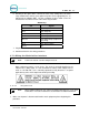
Each wash manufacturer has its own specific color code system and wash relay pin-
outs; therefore, it is important to review the appropriate wash documentation prior to
beginning this portion of the installation.
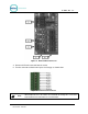
3.7.2 Wiring the Wash Relay Interface
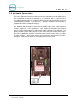
To wire the wash relays, connect the wires that come from the PLC to the appropriate
pin numbers in the phoenix connector using the following procedures:
Note:
The wiring for the Portal TI Wash I/O board is the same as the wiring for the Wash
Select II wash interface.
3.7.2.1 Preparation
• You will need a thin tipped, flat head screwdriver to open and tighten the relay
connections of the Phoenix connector.
• Review the wash manufacturer’s documentation to determine the color codes for the
wiring of the wash pin-outs for your wash equipment before beginning this installation.
• Phoenix connectors are shipped already inserted in the appropriate sockets on the
Wash I/O board.
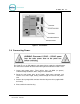
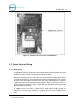
1. Remove the Carrier Board/Wash I/O Board Cover Plate using a 5/16” socket
wrench.
2. Locate the Wash I/O board on the inside lower right-hand wall of the Portal TI
case.
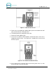
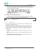
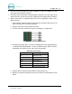
3. On the Wash I/O Board, locate the 10-pin Phoenix connector labeled J17 on the
lower right-hand corner of the Wash I/O board.
Document #: PTL1001