Portal Owners Manual Unitec 443-561-1200• www.StartwithUnitec.
PORTAL PORTAL OWNERS MANUAL This manual describes the functions of the Portal Ti entry system running the Sierra software platform. If further assistance is needed, please contact the distributor from which the Portal was purchased.
PORTAL Document Revision History Software Version 4.43 Portal Rev Release Date 9/2014 1.73 Sierra 3.22/4.33 Portal 1/2014 1.63 Sierra 3.50/4.22 Portal 1.52 Sierra 3.41/4.12 Portal 1.42 Sierra 3.33 Portal 1.34 Sierra 3.12 Portal 1.12 Sierra Changed OS from Windows NT to Windows 7 POS Ready.
PORTAL [THIS PAGE INTENTIONALLY LEFT BLANK] Document Number: PTL1028 Document Title: Portal 3 Owners Manual
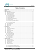
PORTAL Table of Contents 1 Introduction ............................................................................................................... 7 2 Login .......................................................................................................................... 7 3 Set-up Functions ....................................................................................................... 11 3.1 General Site Information .....................................................................
PORTAL 5.6 6 7 8 9 10 Accounts .................................................................................................................. 27 5.6.1 Prepaid and Subscription Accounts .................................................................. 27 5.6.2 Loyalty Accounts ............................................................................................... 28 5.6.3 Fleet Accounts................................................................................................... 29 5.
PORTAL 10.3.1 Setting the Alarm ...................................................................................... 68 10.3.2 Shock Sensor ............................................................................................. 69 10.4 Bill Dispenser ........................................................................................................ 69 10.4.1 Bill Dispenser Location .............................................................................. 69 10.4.
PORTAL Document Number: PTL1028 Document Title: Portal 3 Owners Manual
PORTAL Table of Figures Figure 1. Portal TI Login Screen............................................................................................................... 7 Figure 2. Password Change Screen ......................................................................................................... 8 Figure 3. Site Summary Screen ............................................................................................................. 10 Figure 4. Promotions - Main Screen ......................
PORTAL Figure 39. System Utilities Screen......................................................................................................... 53 Figure 40. Enable Support Mode Screen .............................................................................................. 54 Figure 41. Database Utility Screen ........................................................................................................ 55 Figure 42. Database Compact and Clean Screen .....................................
PORTAL 1 Introduction The Portal is car wash payment system that is designed to work at any in-bay automatic or conveyor and works well for the express exterior car wash. This Owner’s Manual describes the programming features and provides information on daily operations and recommended maintenance. For detailed information on how to install the Portal and for networking information, please see the Portal Installation Manual.
PORTAL Due to PCI compliance, once you login the first time using an administrative password , you will immediately be prompted to change your password to a more secure password that is at least 7 characters long and contains both letters and numbers, as shown below. NOTE: An administrative password is a user that has either “User Management” or “Utilities” access privileges under Setup>Users. For more information on Users, see Section 3.5.
PORTAL NOTE: The new password will also be required to login to the Maintenance screens on the Portal, Sentinel and C-Start units. A keyboard will appear at units that have a touchscreen. For Portals that have a keypad, you either must use a keyboard to login, or you must scroll through the keys on the side of the display to enter your password.
PORTAL Upon successful login, the Summary page of the management application will appear. This screen displays a list of devices present on the local network with a count of washes provided and associated revenue for the current day. Car counts and revenue results from previous days can be viewed by selecting the desired date in the calendar or by entering the start and end dates in the summary data fields. The current day data can be updated by selecting the Refresh button.
PORTAL 3 Set-up Functions The Set-up function are used to program the Portal’s operational settings and for managing system users. Portal programming should be performed during installation by your Unitec distributor, but there are some settings that an equipment owner may wish to change, periodically. This section of the manual describes the programmable features that are available.
PORTAL 3.3.2 Operating Schedule The Operating schedule allows you to automatically set an opening and closing time for your car wash. The message that is displayed when the site is closed can be programmed on the User Interface Set-up Page (described in section 3.3.7). Operating schedules can be configured to vary by day of the week. The operating schedule is disabled by default. 3.3.
PORTAL 3.3.7 User Interface Set-up The User Interface set-up page is used to change messages displayed to customers and adjust ‘time-out’ values for certain user screens. There are several features on this page that an operator may wish to adjust including: Greeting Message Delay – The delay from when a vehicle is detected (at the Portal) until the greeting message is played. Added Services Screen Timeout – The amount of time the Added Services offer screen will be shown.
PORTAL Cash Adjustments – Allows the user to access the cash deposit and removal functions im Maintenance mode. These functions are used to adjust calculated cash balances as change is restocked or cash is removed from the Portal. Accounts and Promotions – Allows the user to set up and manage promotional programs and house accounts. Code and Account Sales – Allows the user to Access the optional console pages (for prepaid wash code sales).
PORTAL 4 Promotions The promotions feature is used to set up and manage various marketing programs. The types of programs that are available include discounts, complimentary washes, fundraisers, and scheduled specials. Reports for tracking and managing these programs are accessed through the menu options on the left side of the promotions management pages (as shown below).
PORTAL 4.3 Fundraisers The fundraiser is a code-activated promotion intended to encourage supporters of an organization to use the car wash. No discount or other benefit is provided to the user at the wash but usage of the fundraiser ‘code’ is tracked and reported. The operator will typically donate a set amount to the organization for each wash purchase where the fundraiser code was entered.
PORTAL 4.6 Promotions Setup Figure 5. Promotions Main Screen The Promotions Setup screen displays the current promotions. They are listed by name, type of promotions, and status. Note that the promotion statuses are ‘active’, ‘inactive’, ‘expired’, and ‘exhausted’. ‘Expired’ means beyond the promotion schedule end date/time. ‘Exhausted’ only applies to promotions that have a maximum usage configured.
PORTAL 4.6.1 Prize Promo Setup Figure 6. Prize Discount Setup Screen 1. To setup a Prize Discount, enter the name of the prize discount. 2. Enter the Prize Rate. The prize rate is the number of wins divided by the number of attempts (in percent). 3. Select a code length form 5-8. The default is 7. 4. Enter the prize expiration date. This can be set from 0-30 days. 0 days means the prize does not expire. The default is 30. 5. If you would like to enable a Schedule, click Enabled and Edit.
PORTAL Figure 7. Prize Voucher Setup Screen 1. To setup a Prize Voucher, enter the name of the prize voucher. 2. Enter the Prize Rate. The prize rate is the number of wins divided by the number of attempts (in percent). 3. Select a code length form 5-8. The default is 7. 4. Enter the prize expiration date. This can be set from 0-30 days. 0 days means the prize does not expire. The default is 30. 5. If you would like to enable a Schedule, click Enabled and Edit.
PORTAL Figure 8. Edit Discount Screen 1. Enter the Name of the promotion. Select Active to enable the promotion. 2. Select the method of the promotion from the drop-down menu. For Discounts and Free Washes, the methods are: Codes, Tokens 1-4, and VIP Coupons 1-3 and Mars Coupon. If Mars Coupon is selected, you will need to enter the 4-digit code from the coupon. For a Fundraiser, you may only choose Codes. For a Special, there is no method to choose from. 3.
PORTAL 8. Click Save. If you wish to change or delete a wash, click Remove from List by that wash. 9. Click Save. 4.7 Promotions Reports 4.7.1 Status Report The status report lists all promotions that have been configured and provides status information, as shown in the sample report below. The status will be active, inactive (disabled), exhausted (max uses limit reached) or expired (end date is reached).
PORTAL Figure 11. Sample Promotions Usage Report 5 House Accounts The accounts module is a product option that allows house accounts to be set up and managed in the Sierra server application. Four account types are available: prepaid, subscription, loyalty, and fleet accounts. Accounts can be configured for redemption by a magnetic stripe card, numeric code or RFID tag. The Accounts module also includes reports for tracking account status and usage.
PORTAL You may reload the account without reentering all information, and the customer may also reload his account at the entry unit. If the balance of the account is insufficient for the purchase, the customer will be asked if they’d like to recharge the account. If they choose to do so, they’ll be prompted to add payment and the account will be recharged for the amount that’s defined in the account program.
PORTAL Frequency Reward – select wash that will be awarded Expiration – Days in which rewards must be claimed (default will be no expiration) Accounts will be activated from the management pages by selecting the associated loyalty program and entering the customer-specific data, including: 5.4 User name and contact details (address, e-mail etc.
PORTAL Figure 12. Account Program Screen To setup a new account program, select from either Pre-paid, Subscription or Loyalty from the drop-down menu below the table and click Add New Account Program. The Edit Account screen will be displayed. To edit an existing account program, click Edit next to that program. 5.5.1 Pre-Paid Account Program Setup Figure 13. Pre-paid Account Program Edit Screen 1. Enter the name of the account program.
PORTAL 2. Select the type of account from the drop-down menu. A product-based account is useable for only (1) wash product (which is selected from a drop down list). Monetary accounts can be used for any wash. NOTE: Prepaid accounts can be monetary or product based; subscription accounts are product based. 3. Enter the Issue Price (or selling price) that will be reported when a new account is issued (or sold) and then enter the Value for which the account can be redeemed.
PORTAL 8. Enter the name of the account program. Chose whether or not to force a receipt with each transaction. 9. Select the product from the drop-down menu. 10. Enter the Issue Price (or selling price) that will be reported when a new account is issued (or sold) and then enter the Value for which the account can be redeemed. This field is not present on Subscription accounts. 11. If desired, enable and enter the recurring bill amount. This amount will show up on reports ONLY.
PORTAL Figure 15. Prepaid Account Edit Screen The account set-up page will show values that were set-up for the account program but additional data will need to be entered for the account holder as follows: Last and First name of the Account holder. A mailing address can be entered if desired by selecting the ‘details’ tab. Redemption method – select code, card, barcode or RFID (Subscription accounts only) from the drop down menu. Number – Enter code, card number or RFID tag number. 5.6.
PORTAL Figure 16. Loyalty Account Setup Screen 5.6.3 Fleet Accounts Fleet Accounts are set-up and managed directly through the ‘Accounts’ option (not the ‘Programs’ option). Account set-up is a 2-step process. The first step will be to set up and save the fleet business account. The 2nd step will be to add users (drivers) under the account. From the main Accounts page select Fleet as the account type and click the Add New Account button.
PORTAL Figure 17. Edit Fleet Account To set-up the fleet account: 16. Enter the business name for the account in the Name field. 17. Select the account type as monetary or product based. For product accounts, the associated wash product will need to be selected from the drop down list of available products. 18. Enter the value of discount that should be applied to the fleet customer’s billing statement. Discounts can be set for a dollar value or a percentage. 19.
PORTAL Figure 18. Edit Account User To add a new user, 24. Enter the first and last name of the account user 25. Select the redemption method (code, card, barcode or RFID Tag) 26. Enter the code, card number or RFID tag number for the user 27. Click Save. 5.7 Account Reports 5.7.1 Status Report A sample status report is shown below.
PORTAL Figure 19. Sample House Account Status Report 5.7.2 Listing Report This report allows you to export a list of account holders in .csv format. The exported file includes the account holder name and contact information, account number, and enrollment date.
PORTAL 5.7.3 Loyalty Report The Loyalty Report provides a list of all members, their account numbers, uses, uses per month, and rewards information, plus any discount. Issued Account Name Account # Uses Andrews, Ed Bruschi, Ted Carlson,Jim Francis, Lois Harris, Jane Jackson, Lou Ortiz, David Smith, John Wilson, Terry 59632159 84965327 65843215 33256984 54213985 44869532 95487623 25644459 15789652 26 14 9 6 4 22 18 12 7 Claimed Expired Average Uses/Month Rewards Rewards Rewards Discount $1.
PORTAL Figure 21.
PORTAL Dates of billing, when the payment is due, and the amount due The payment address User Name and Account Number (either card, code or RFID tag) Day the car wash was used The wash package that was purchased. Usually, a wash package is assigned to the account in setup. Price of the wash package used. The price is totaled at the bottom of the column. Amount of discount that is applied to the account (if any). The discount if totaled at the bottom of the column.
PORTAL 5.7.5 Sales Report Figure 22. Account Sales Report The account sales report provides a list of prepaid account sales and account reloads during a user defined date range. A sample report is shown above. Account Name and Number Program – indicates whether an account program was used for this account. Date – day account was purchased. Sales type -- indicates whether the entry is for a new account that was sold (issued) or a reload.
PORTAL Price -- indicates the amount due from the account holder. Employee ID – indicates the system user who issued or reloaded the account. 5.7.6 Account Transaction Report Figure 23. Account Transaction Report The Account Transaction Report displays all transactions over a user defined date range. The report can be filtered to show transactions for all accounts, all accounts of a certain type (e.g. subscription, fleet …) or a single account.
PORTAL 6 Reports The Reports function allows you to view accounting information and product usage, filtered by ranges and dates you specify. When a report is generated, the associated data will appear on the screen with Print and Save functions. By selecting the Print button, you can print a copy of the report at your local printer. The Save function allows the report data to be saved in .CSV format so it can be viewed and/or sorted in standard 3rd party software applications (such as Microsoft Excel).
PORTAL 6.1 Site Revenue Report Revenue reports can be generated for the current business day, previous day or for a user specified date range. From the report view, the user can print a report copy or save an electronic version in .CSV format. An example report is shown below with descriptions of the included data.
PORTAL Qty Revenue Account Sales $25 Gift 5 Deluxe Card 5 Express Card Total 7 3 4 14 $175.00 $120.00 $120.00 $415.00 Accounts Reloads 5 Deluxe Card 5 Express Card Total 8 5 13 $320.00 $150.00 $470.00 Site Totals Tax Collected Total payments Fundraisers Due Net Revenue Revenue Prepaids Subscription $2,448.30 $1,029.00 0.00 38.55 $2,486.85 $1,029.00 0.00 ($7.00) $2,479.85 $1,029.00 0.00 Figure 24.
PORTAL 6.2 Sales Report The Sales report shows the products that were purchased in the reporting period. This report can be generated for a specific payment device or for all devices on site. The available report periods are current day, previous day or a user-specified date range. Sales reports can be printed or saved in .CSV format. An example report is shown below with descriptions of the included data. Figure 25.
PORTAL Wash Activations - Provides a count of washes dispensed, broken down by wash type, and includes washes dispensed using codes or maintenance accounts. The usage metric shows the percentage of activations for each wash type. Self-serve wash packages are displayed by purchase type - cash, credit, house account, or maintenance account. Added Services - Provides a count of added services that were purchased, broken down by service type.
PORTAL 6.3 Cash Report The cash report provides details on cash, coupons and tokens that were received and dispensed during the business day. The report can be generated for the current day (as a real time snapshot) or for any previous day. An example report is shown below with descriptions of the included data. Figure 26.
PORTAL from a cash acceptor or dispensing device. The adjustment record shows the date and time of the event, the user ID of the employee that performed the adjustment, and lists the amount of cash that was added or removed. The total amount of cash that was added and removed through these adjustments should match the associated entries in the Cash Summary section. The bottom of the report displays the cash information for each device.
PORTAL Figure 27. Sample Transaction Report When the transaction report is viewed, a “details” link will be displayed for each record. By clicking on this link, the user can view and print a more detailed record of the transaction. An example of this detailed view is shown below. Figure 28.
PORTAL 6.5 Code Listing Report The code listing report is applicable to sites that use the optional POS interface or console for wash code sales. It can be used to check the status of a specific code by entering all or part of the code number. To generate a complete list of wash codes in memory, leave the code field blank and select the Run report button. Figure 29. Sample Code Listing Report The wash codes currently stored in memory are listed in chronological order.
PORTAL 7 Sales The Sales tab displays and functions as a Point of Sale console interface. You must first set up the Sales screen in the POS Interface in order for this screen to be populated. For further instruction, please see Section 3.6. Figure 30. Sales Screen The Sales screen function keys are color-coded. Washes are blue and reports are red. Account, reloads, rewashes and the check and void code functions are teal.
PORTAL To purchase a wash package, select one of the washes then click Purchase. Figure 31. Purchase Wash Package Screen A code will be generated and displayed on the screen. You may then print the code from the POS printer or from the print function of your PC. Figure 32.
PORTAL To purchase a new account, click on the account: Figure 33. Account Purchase 1. 2. 3. 4. Select code or card. Enter the account number. Enter the account holder’s name. Click Purchase to finalize the account purchase.
PORTAL To reload an account, click Reload and enter the account number. Figure 34. Reload Account Screen Ensure the account holder’s information is correct, then click Reload. Figure 35.
PORTAL To issue a rewash code, click Rewash then select the wash to issue the code: Figure 36. Rewash Selection Screen Figure 37.
PORTAL To print a report, select the report type. If you would like to select a date other than the current day, select Change Dates. You may select the current day, select the previous day, or select a date range, then click Done, then Print Report. NOTE: The Report functions on the Sales page are for console users ONLY. Figure 38.
PORTAL 8 Utilities The Utilities tab allows you to view the current server version, view the current C drive version, view any hot fixes applied, view the IP address, set the system date and time, backup and restore the databases, view the event log, and upload software updates. Figure 39. System Utilities Screen The System Utilities screen displays the current installed server software version, installed hot fixes (if any), the server IP address as allocated by the router, and the database ID.
PORTAL 32. IMPORTANT NOTE: For WashPay systems, ensure that there are no pending transactions before restarting or shutting down the server, or those transactions will be lost. 8.1 Enable Support Mode Enable Support Mode is a feature that allows Unitec Customer Service to access and troubleshoot the server via remote access. If your devices are having problems, call Unitec Customer Support at 1800 Click the button to access the next screen. Figure 40.
PORTAL 8.2 Database Management Figure 41. Database Utility Screen The Database Utility screen is used to backup and restore the Sierra Server databases. Database back up files can be used to restore operation of the system in the event of a catastrophic event. To minimize the potential for lost sales data, regular back-ups should be performed. The software version, date and time of previously created back-ups are displayed on the screen. 8.2.
PORTAL Enter a start date. Click Delete Transactions. NOTE: All transactions prior to that date will be deleted, so make sure to create a database backup and hardcopy backups before performing this function. 8.2.2 Delete Old Codes The Deleting Old Codes function allows you to erase old POS codes from the database to remove old unused codes from reports and free up memory. To delete old codes: Figure 43. Delete Old Codes Screen Enter the number of days. Click Delete Codes.
PORTAL 33. Click Enable Automatic Backups, then select the location, either the D drive or a thumbdrive, from the drop-down folder. Enter a time to perform the automatic backup. Click Save. 34. To create a backup: Make sure all devices are idle. You may choose where to save the backed-up data. To save backups on a separate device, a thumb drive should be connected to one of the USB ports on the primary carrier board. 35.
PORTAL 8.3 Files Figure 45. Files Screen The Files screen allows you to load software update files and post sale video files to the unit. Updates are provided on a thumbdrive that is to be connected to the USB port on the primary carrier board. With the thumbdrive installed, click the Load Files button. The thumbdrive should be listed as a source location. Select it and click Upload. Note: Video files must be in .wmv format.
PORTAL 9 Maintenance Functions The Maintenance screen displays the current status of the devices located in the Portal unit. This screen is only accessible from the Portal, and will appear after you turn the key in the lock and login to the unit or by entering the code 4401 at the Sales screen. Figure 46. Portal Maintenance Screen The Portal Maintenance screen provides access to the following screens. To display these screens, press the button beside the item you wish to display.
PORTAL Cash Functions – This key allows an authorized user to deposit or remove cash from the Portal vault. This will reset the cash totals. Shutdown – This key is used to shut down, restart the Portal unit, or reload the device profile without having to open the door. (Note: The shut down function should always be performed before turning off power to the Portal). 9.1 Cash Functions Cash functions allow an authorized user to deposit or remove cash into or from the Portal vault.
PORTAL Figure 48. Cash Removal Screen The Cash Removal screen allows you to keep track of the cash removed from the Portal. When removing cash, you must remove ALL cash from that selected device in order for the Portal to report accurate amounts. Select the device you wish to remove cash from and click OK. Upon completion of the withdrawal, the Portal printer will issue a receipt listing the amounts removed and updated cash balances.
PORTAL 9.2 Shutdown The Shutdown feature allows you to shutdown or restart the Portal. Once the Portal software is shutdown, you may shutdown the unit at the main power switch inside the unit. Note: The shutdown function should always be executed before powering off the Portal. The reload feature allows you to reload the device profile. Figure 49.
PORTAL 10 Component Operation and Maintenance This section of the manual describes the normal operating procedures and basic troubleshooting and repair techniques for each of the system components. The following procedures are designed to provide you with the hardware troubleshooting and service information you need in order to provide your customers with the highest quality service possible. When troubleshooting any issue, verify that the power supply is providing power to the affected component.
PORTAL Figure 50. Portal TI Front View Visible Components 10.1.2Inside the Portal TI Door Assembly The system components built into the Portal TI Unit door are laid out as shown in the following figure.
PORTAL Figure 51.Components Inside the Portal TI Door 10.1.3Inside the Portal TI Unit Case The following figure provides a block diagram showing the components located inside the Portal TI. This drawing is intended to provide general component location information only.
PORTAL Figure 52. Block Diagram of Components Inside the Portal TI Case Inside the Portal TI unit case, you will find the following sub-assemblies: Carrier Board – This sub-assembly contains and protects the carrier board. It is located inside the Portal Case on the right-hand wall. Wash IO Board – This board and mounting plate is located on the right-hand wall of the Portal TI case below the Carrier Board sub-assembly.
PORTAL The Coinco Bill Validator logic board is mounted on the inside left wall of the Portal TI. It is mounted with the diagnostic LED facing forward for easier accessibility. Figure 53. Block Diagram of Components Inside the Cash Vault 10.1.5System Cabling System cabling comes into the Portal TI through the cable entrance ports located on the bottom right hand side of the unit. Wash cabling will be directly connected to the Wash IO Board at installation.
PORTAL 1. Remove the coin hopper from the unit. 2. Remove all coins from the hopper. 3. Use a damp rag to clean any metal dust that may have accumulated on the exit ramp. 4. Remove the two side screws that hold the bottom support bracket and pull the main hopper cube from the hopper assembly. 5. Use a Q-Tip or Iso-swab to clean the coin exit slot. 6. Remove the top part of the hopper by sliding the red lever on the side of the hopper downward. Slide the top part of the hopper upward to remove it. 7.
PORTAL 10.3.2Shock Sensor The Portal TI is equipped with a shock sensor, located in the upper middle of the unit door, to detect a person attempting to vandalize or break into the unit. It is a small white box adhered to the door. 10.4 Bill Dispenser The Bill Dispenser allows you to dispense cash from the Portal as change. Many customers choose to dispense $5 bills as well as the $1 coin and quarters.
PORTAL 10.4.3Bill Dispenser Operations Components The following figure shows the bill dispenser with the primary components labeled. Figure 55. Bill Dispenser Parts Manual Knob - This knob is used to advance the bill transportation devices manually in the event of a bill jam. Reject Area - If the bill dispenser senses an error in the bills while dispensing (such as two bills instead of one), it will reject the erroneous bills and send them to the reject area instead of dispensing them.
PORTAL Caution: If you pull the bill too hard, the belt will come off the pulleys. Figure 56. Manual Knob and Transportation Area 3. After removing the jammed bill, verify that the transportation belts are still properly aligned on their respective pulleys. 10.4.4.2 Removing a Jammed Bill from the Dispensing Area 4. While pressing down the metal fitting of dispensing roller, turn the manual knob and gently remove the jammed bill.
PORTAL Figure 57. Removing a Jammed Bill 10.4.5Loading the Bill Dispenser The first time the bill dispenser activates after being re-seated into the Portal TI, there will be a fivesecond delay while the dispenser initializes before it dispenses the bill(s). Normal dispense time (one to two seconds) will resume after this initial activation.
PORTAL Figure 58. Loading Instructions 12. Slide back the spring-loaded bill holder until it locks.
PORTAL Figure 59. Loading the Bill Dispenser 13. Insert the bills in groups of 100 (up to 1,200 new bills). 14. Slide the bill holder back into position. 15. Close the cassette door. 16. Rotate the bill dispenser counter-clockwise until it snaps into place. 17. Slide the bill stacker back into the Portal TI.
PORTAL 10.4.6Maintaining the Bill Dispenser The following photos show you how to clean the pick roller and the sensor in the bill dispenser. Figure 60.
PORTAL Figure 61.
PORTAL 10.5 Bill Validator The bill validator allows customers to pay for their washes using bills. The standard Portal TI comes equipped with the Mars bill validation unit. Units built prior to 2010 have Coinco bill validator units. 10.5.1Mars Bill Validator The Mars bill validator is provided as the bill validator from the manufacturer since 2010. 10.5.1.1 Removing the Bill Stacker The bill stacker will hold up to 1,000 bills and is designed to allow quick and easy removal of stored money.
PORTAL Figure 63. Mars Bill Validator—Top View 10.5.1.2 Replacing the Bill Stacker To replace the stacker, perform the following steps: 1. Position the stacker behind the Mars Bill Validator with the hinged doors on the side, and the back of the stacker facing away from you. 2. Place the stacker against the bill validator. 3. Align the tabs on the bill stacker just above the guide slots on the bill validator. 4.
PORTAL Figure 64. Mars Bill Stacker Replacement 10.5.1.3 Mars Bill Validator Flash Codes The Mars Bill Validator is equipped with an internal diagnostic LED flash code system. This LED flash code system is used to alert the operator of a failure or to indicate a need for servicing. The flash code LED is located in the lower section of the validator, below the stacker. See the following figure for the LED location.
PORTAL Figure 65. Mars Flash Code LED The LED will repeat a specific number of flashes. Each number of flashes corresponds to a specific problem. The following table lists the meaning of each set of flashes. Many of these problems may be easily corrected without the need for technical assistance. Table 2.
PORTAL # Flashes 10.5.1.4 Diagnostic Code Description Continuous slow Unit failure, replace unit Continuous fast Stacker full LED on Ok LED off Power off Removing the Mars Bill Vali dator From the Portal TI Perform the following steps to remove the Mars Bill Validator. 1. Open the cash vault. 2. Remove the bill stacker. 3. On the inside of the vault door, remove the four 5/16” mounting nuts on the sides of the Bill Validator. 4.
PORTAL Figure 66. Mars with Lower Housing Figure 67.
PORTAL 10.5.1.6 Cleaning and General Maintenance The AE2600 series will not need cleaning as often as magnetic sensing bill validators. If cleaning is required, use a soft cloth moistened with mild, non-abrasive detergent. 10.6 Card Reader The card reader may be used with the Credit option or just for fleet cards and pass cards. 10.6.1Cleaning the Card Reader The internal card reader sensing devices accumulate dirt over time.
PORTAL Symptom Card reader not recognizing card inserted. Possible Cause Bad Display I/O board. Test Verify 5V power LED on display I/O board. Disconnect Card Reader connector from Display I/O Board. Resolution Replace Display I/O Board. Short pins 1 & 7 and release. If you do NOT get a “Bad Card Read”, the Display I/O Board is bad. 10.7 Coin Acceptor This component allows the Portal TI to accept U.S. quarters, dollar coins and up to four different bi-metal tokens. 10.7.
PORTAL Figure 68. Outside/ Inside of the IDX You must answer the following questions before proceeding with the programming of the IDX coin acceptor. Do you want to accept tokens? How many different tokens will your site have? How much will each token be worth? Refer to the following table to determine which rotary-switch position corresponds to a particular coin output. Table 4.
PORTAL 1. Set the rotary-switch to the position labeled number 5. 2. Press the button located immediately to the left of the switch once. 3. Drop six different dollar coins through the acceptor and verify that the light (LED) blinks after the last coin has been entered. 4. Move the rotary switch back to the position labeled ‘0’. 10.7.4Programming the IDX to Accept Quarters Follow the steps below to program the IDX to accept quarters. 1.
PORTAL If more tokens are required, refer to Programming the IDX Acceptor to get the switch locations for that particular token, and then press the push-button the number of times that is equal to the number of pulses to be sent for that token. 10.7.6Erasing IDX Programming If you need to erase programming or start over, use the following procedure: 1. Remove the front cover from the IDX acceptor. 2. Set the rotary switch to the position that corresponds to the coin you wish to re-program or erase. 3.
PORTAL Figure 69. Block diagram of the Hopper Cage The Portal TI is equipped with a Suzo Mark II coin dispenser, which is embedded in a proprietary Unitec design. The dispenser is able to hold/dispense up to 2,400 quarter-sized coins. It is located inside the Portal TI case in the hopper cage. 10.8.1Removing the Hopper To remove your hopper, pull the Hopper Drawer forward. As you pull it forward, lift on the rear to disengage the guide pin from the hopper cage. 10.8.
PORTAL the weight of the coins. When pouring coins into the dispenser, you must direct the coins at this inclined plane to protect the moving parts at the bottom of the hopper. Follow the instructions below to fill the coin hopper. 1. Open the door and vault of the Portal TI. 2. Remove the appropriate hopper. 3. Pour the replacement coins into the large opening at the top of the hopper assembly. Remember to direct the coins toward the inclined plane. 4.
PORTAL Figure 70. Remove Hopper Coin Bucket 3. Gently lift the coin bucket from the hopper dispenser and set it aside. Be careful not to damage the sensor wire connected to the side of the coin bucket. 4. Separate the black hopper cube from the center of the metal body of the assembly by pressing in the round red locking tab while pushing the black hopper cube forward. 5. Slide the red locking clasp downward. Figure 71.
PORTAL 6. Slide the top piece of the black plastic hopper up and off to expose the dispensing wheel. Figure 72. Hopper View - Top Removed 7. Remove the dispensing wheel. Figure 73. Dispensing Wheel Removed 8. Remove the guide arm cover from the coin exit opening.
PORTAL Figure 74. Guide Arm Cover Removed 9. Using a screwdriver, gently pry off the old hopper arm. Be very careful not to break the pins that hold the arm in place. 10. Place the new hopper arm into the slot exactly as the old one was. 11. Place the new hopper wheel into the plastic hopper exactly as the old one was. 12. Once the new guide arm and dispensing-wheel have been replaced, reinstall the coin guide arm cover. 13. Slide the black plastic top back onto the hopper-cube assembly.
PORTAL Figure 75. Hopper View - Coin Exit Opening and Chute 10.9 Credit Modem With the purchase of the dial-up option, you will receive a DataTran modem. This modem receives power from one of the 115VAC outlets inside the unit. These outlets should only be used for Unitec certified optional equipment and are limited to 500mA output each. The modem is connected to the Carrier board via a serial cable. One end of the cable is attached to the modem and the other end to the Carrier board.
PORTAL To adjust the proximity sensor: 1. Place a flat surfaced object approximately 12” x 12” in front of the proximity sensor at the MAXIMUM distance you wish the proximity sensor to detect approaching vehicles (at least 36”). 2. Briefly press the TEACH button. The yellow LED will flash off then on again after 2 seconds. 3. Place the flat object in front of the proximity sensor at the MINIMUM distance you wish the proximity sensor to detect approaching vehicles (at least 6”). 4.
PORTAL The Main Door Lock switch is the black switch on the lock assembly. This switch closes the circuit when the door is closed and locked, and opens the circuit when the door is open. The Lock/Arm LED (LED 6) is located just under J19 on the Display IO board. The Lock/Arm LED is lit when the Main Door Lock switch circuit is closed (door is unlocked). The Maintenance mode has Input tests to show the status of each input as read by the software.
PORTAL 10.13 Thermal Printer The Portal is equipped with the Hecon thermal printer. The Hecon printer uses paper rolls 2.28” to 2.36” wide by up to 400’. The thermal printer is capable of printing graphics and barcodes, as well as system reports. Figure 76. Hecon Printer The following sections contain information and procedures important for peak operating performance.
PORTAL 10.13.1 Replacing the Printer Paper Replace printer paper when you see a red mark running down the side of the receipt or the unit is reporting Paper low. 1. Insert the new paper roll on the paper carriage at the bottom of the printer. The paper roll should be oriented such that the end of the paper is at the top of the roll. The paper will automatically feed into the printer when the power is on. 10.13.2 Clearing a Paper Jam Follow the steps below to clear a paper jam. 1. Open the Portal door.
PORTAL Appendix A: Themes Standard (Default) Theme Autumn Theme Document Number: PTL1028 Document Title: Portal 3 Owners Manual
PORTAL Flag Theme Sky Theme Document Number: PTL1028 Document Title: Portal 3 Owners Manual
PORTAL Spring Theme Summer Theme Document Number: PTL1028 Document Title: Portal 3 Owners Manual
PORTAL Water Theme Winter Theme Document Number: PTL1028 Document Title: Portal 3 Owners Manual