
Owner's Manual Instruction Manual


P O R T A L
Document Number: PTL1028
Document Title: Portal 3 Owners Manual
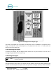
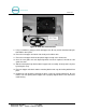
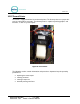
The Main Door Lock switch is the black switch on the lock assembly. This switch closes the circuit when
the door is closed and locked, and opens the circuit when the door is open. The Lock/Arm LED (LED 6) is
located just under J19 on the Display IO board. The Lock/Arm LED is lit when the Main Door Lock switch
circuit is closed (door is unlocked).
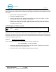
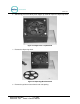
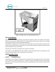
The Maintenance mode has Input tests to show the status of each input as read by the software. If the
Maintenance mode indicates a problem with one of the switches, perform the following procedure:
1. Unplug the affected switch.
2. Use a screwdriver to short out the pins on the corresponding board. Shorting the pins
should cause the LED to turn on.
3. If the LED does not turn on, there is something wrong with the board. If the LED does turn
on, but the switch is not working correctly, then there is something wrong with the switch
(or possibly a mechanical part that interacts with the switch).