MS860G WiFi Bar Code Scanner REV.
TABLE of CONTENTS INTRODUCTION ............................................................................ 1 INTRODUCTION ..................................................................... 1 QUICK START ......................................................................... 2 SCANNER PARTS:.................................................................. 5 CRADLE PARTS...................................................................... 7 CHARGING THE SCANNER:........................................
MS860G WiFi Manual
INTRODUCTION INTRODUCTION The MS860G WiFi laser bar code scanner is one of the newest members of Unitech’s MS series. The MS860G incorporates the latest WiFi technology, making it ideal for real-time bar code data collection in warehouse, loading dock, inventory, back office, document tracking, retail environments - anywhere cables would restrict movement or limit access. The incorporated 802.
INTRODUCTION QUICK START 1. Connect the plug of the power adapter into the power jack on the cradle, and connect the power adapter into an AC outlet. You will hear a beep, and the Power Status and Charging Status LEDs on the top of the cradle will glow green. 2. Use an unfolded paperclip to push down the battery power on/off internal switch located inside the round hole on the yellow warning label underneath the scanner.
INTRODUCTION IMPORTANT NOTES • "ACK” helps avoid data loss during an Access Point (AP) power disconnection. To turn “ACK” on, follow the steps below: Print out pg. 65 – RS232 Settings Scan: Enter Group 4 C5 1 Exit After “ACK” is turned on, the scan data transmission rate might be a little slower, depending on your wireless network condition.
INTRODUCTION SCANNER AND ACCESSORIES: MS860G-W8A: MS860G WiFi laser scanner w/US plug MS860G-W8B: MS860G WiFi laser scanner w/UK plug MS860G-W8E: MS860G WiFi laser scanner w/UP plug 400479: Unitech MS860G WiFi Scanner user guide CD 400480: Unitech MS860G WiFi Scanner quick start guide sheet *Scanner Configuration Manager: Windows based software providing a user-friendly interface for easier scanner configuration. *Available on the Unitech website – www.unitech-adc.
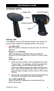
INTRODUCTION SCANNER PARTS: Scanner LED The MS860G has one LED indicator located on the head of the scanner which indicates the operating status of the scanner. Red LED is ON When the scanner attempts to read a bar code, the LED will glow red. Single Green LED Flash When the scanner successfully reads a bar code the scanner LED flashes green once, and you will hear a single beep. Flashing Green LED 1.
INTRODUCTION Buzzer The MS860G provides audible feedback while it is in operation. These sounds indicate the operating status of the scanner. One High Tone Beep The scanner will beep once after successfully reading a bar code. One High-Low-High Beep After scanning a ‘begin configuration’ bar code (“Enter Group 5”, for instance), the scanner LED will flash green while the scanner simultaneously gives one high-low-high tone beep.
INTRODUCTION CRADLE PARTS Cradle LEDs The MS860G charging cradle has two LED indicators (power on/off status and battery charging status). Power ON/OFF Status LED stays ON When the power adapter plug is connected into the power jack on the cradle, and the power adapter is connected into an AC outlet, the cradle will beep, and the LED on the top of the cradle will remain on. Battery Charging Status LED remains Red The red LED indicates the scanner battery is charging.
WiFi INTRODUCTION CHARGING THE SCANNER: Prior to performing any operation with the scanner, make sure it has been fully charged. How to determine if the scanner needs recharging: 1. During operation, a flashing red scanner LED indicates the scanner has low power. 2. When the trigger is pressed and a scan laser line is not visible (do NOT look directly into the scanner), the scanner has no power. Make sure the scanner is not merely switched off. To charge the scanner, place the unit into the cradle.
WiFi NETWORK SETTINGS INTRODUCTION The MS860G WiFi is designed to connect to your computer(s) via the existing wireless network through one of its Access Points (APs), thereby eliminating the dedicated wireless receiving unit required by other types of wireless scanners. Integrating the MS860G into the wireless network is the same as integrating any other piece of wireless hardware, requiring that you give it its own unique IP address, which can be obtained from your network administrator.
WiFi NETWORK SETTINGS So, two things must be configured: the MS860G’s Wireless Network settings, and the host computer’s Virtual Com Port settings. Consult your network administrator for the appropriate network wireless settings for your MS860G which must be manually configured via Scanner Configuration Manager or bar codes (see below and pages 24 to 39). VCOM should automatically create a “virtual com port” for the Access Point to communicate data through.
WiFi NETWORK SETTINGS 1. Application Connectivity TCP Client Mode: TCP client#1 TCP server AP SSID : wlandemo Default SSID : wlandemo Default IP : 192.168.1.240 User name : admin Password : password Destination IP : 192.168.1.2 Destination Port :10002 (Vcom port 2) IP : 192.168.1.2 Server Port:10002 for Vcom port#2 Server Port:10012 for Vcom port #12 (VCOM configuration ref Figure 2 ) TCP client#10 Default SSID : wlandemo Default IP : 192.168.1.
WiFi NETWORK SETTINGS 2. Installation Procedures: Step 1: One should prepare an access point and change its SSID to wlandemo. Step 2: Once SW1601T attached to Access Point, one may use Monitor.exe to Find SW1601T & its IP address, even ones PC and SW1601T are in different subnet. Note: one may click re-scan button to find all the SW1601T in the subnet (Figure 3). Figure 3 re-scan function Step 3: Configure SW1601T by monitor 1. Change SW1601T’s IP address (1) Click “Configuration”.
WiFi NETWORK SETTINGS Figure 4 Networking setting page (4) Click “OK” to configure the setting, and it will pop-up Authorize page, one may input the password and then click “Authorize” button to make the setting effective (Figure 5). Note: the default user name is “admin”, password is “password”. Figure 5 Authorize page (5) After reboot, the settings should be changed to new settings.
WiFi NETWORK SETTINGS 2. Change Virtual COM setting: (1) Click “Configuration”. (2) Select “Virtual COM” -> it will pop-up Virtual COM setting page (Figure 6). Figure 6 Virtual COM & TCP server Settings (3) One may select “Select Port” and then click “Set” to add Virtual COM Port, after configure successful the port selected should change to “used” state and “Advanced button” should be enabled, one may also click “Advanced button” to configure Virtual COM further.
WiFi NETWORK SETTINGS (4) One may use the Default Server port & Server IP to connect Server IP (TCP server) Note: 1. The PC which run moniter.exe utility should detect the IP address itself and the IP address should be act as TCP server if Server IP is different from the monitor.exe detected one may assign it by oneself. 2. One shouldn’t change the Server port & Server IP if one want to use the PC which run moniter.exe utility to act as TCP server. 3.
WiFi NETWORK SETTINGS After click “Config by IE”, it should pop-up the web page below: 3. Software Installing SW1601T wireless-Serial Server is shipped with default settings shown in the following table: Property Default Value Default SSID wlandemo IP Address 192.168.1.250 Gateway 192.168.1.254 Subnet Mask 255.255.255.0 User Name admin Password password RS232 Setup 38400, None, 8, 1, No flow control, Type: TCP client, Destination IP: 192.168.1.
WiFi NETWORK SETTINGS 2.3 Configure by web server Step 1. Make sure ones PC is located on the same subnet as SW1601T. Step 2. Open a web browser, then enter in the IP address of SW1601T to be configured. Note: Default user name is admin and default password is password. Step3. SW1601T’s network, Basic Setup、Radio、Security and RS232 Setup settings should be configured in different web pages. Step.4. Click “Apply” button to save settings and make the change effective.
WiFi NETWORK SETTINGS RF Channel There are 11 potential RF (Radio Frequency) Channels, numbered 1 through 11, to communicate over, and your MS860G and the nearest Access Point will use one of them. Because the MS860G and the AP will sort this out for themselves, it is not necessary for the user to specify a channel, however, a default RF Channel is provided by the MS860G as a starting point. WEP WEP (Wireless Encryption Protocol) is a security key for communicating with an access point.
WiFi NETWORK SETTINGS IMPORTANT: Once you have completed the network configuration for the scanner, VCOM will be required to configure the virtual com port, which means the VCOM utility must run in the background. Some Access Points may not be able to re-connect to the MS860G after it’s been out of range. In this case the scanner will need to be powered off and powered on again, and the VCOM communication must be re-started. VCOM Utility supports Windows2000 and XP.
WiFi NETWORK SETTINGS USING BAR CODES TO SET SCANNER NETWORK: The WLAN default settings are shown below. WLAN Default Settings: Default Setting Item IP Address IP Subnet Mask Gateway IP Address SSID RF Channel WEP Authentication Type 192.168.1.250 255.255.255.0 192.168.1.254 wlandemo 6 Disabled Auto Use the TCP/IP barcode chart on page 62 and the ASCII Chart on pages 65 to 68 to configure your scanner to your own network settings, as the example below: SSID: MySSID IP: 192.168.1.100 Mask: 255.255.255.
WiFi NETWORK SETTINGS General Command List: MODE SSID CHAN PSMODE WEP DEFAULT SAVE EXIT SE BAUD AA WK WKID IP MASK GW DHCP , Set network mode , Set SSID <1 - 14>, Set channel <1 / 0>, PS mode ON/OFF <1 / 0>, WEP ON/OFF Restore configuration to factory default Save configuration to flash Save configuration to flash Save and exit configuration <0 / 1 / 2 / 3>, Set RS232 Baudrate , Set Authentication Algorithm <1 - 4> <1 - 4>, Set
WiFi NETWORK SETTINGS 7. WEP Turn WEP on or off Example: WEP Space 1 CR (turn on WEP) Example: WEP Space 0 CR (turn off WEP) 8. WKID Set which WEP key that you want to use, of which you have four. Example: WKID Space 1 CR (use WEP key number 1) Example: WKID Space 2 CR (use WEP key number 2) Example: WKID, Space 3 CR (use WEP key number 3) Example: WKID Space 4 CR (use WEP key number 4) 9. WK Set WEP key association with a WEP key number.
WiFi NETWORK SETTINGS 13. SAVE Save the configuration settings Example: SAVE CR 14. SE Save the configuration settings and reboot Example: SE CR 15. DEFAULT Restore configuration settings to factory default, and automatically reboot the module Example: DEFAULT CR 16.
SCANNER CONFIGURATION MANAGER Scanner Port Scanner Port parameters refer to scanner functions (such as Double Verification, Scanning Mode, etc.) and some simple data editing features. For more powerful data editing, refer to the Data Editing section starting on page 37. Terminator The Terminator is a command that follows the input of bar code data.
SCANNER CONFIGURATION MANAGER Scanner Port, continued Use Code ID The Code ID function can be used to identify the type of bar code that is being scanned by inserting an identifying letter (refer to the chart at right) at the beginning of the bar code input. For example: if the Code ID function is on, and a bar code string of “54321” was output as “M54321”, the bar code would thus be identified as type Code 39. Default is “No”.
SCANNER CONFIGURATION MANAGER Scanner Port, continued Scanning Mode Scanning mode refers to the method by which scans are initiated, whether by pressing a trigger, or simply presenting a bar code to a continuously reading scanner. Scanning can occur in seven different ways: • Trigger scan causes the scanner light to remain on as long as the trigger is depressed, whether the bar code is recognized or not.
SCANNER CONFIGURATION MANAGER Scanner Port, continued Aim Function for Long Range Engine The Aim function causes a laser scanner to output a “pin-point” aiming aid for a specified period of time (see below) to enable a user to more easily scan distant bar code labels. Default is “No”. Aiming Time for Long Range Engine The Aiming Time function specifies the duration of the Aim Function (see above) The length of duration can be specified from 500ms to 2 seconds, in half-second increments.
SCANNER CONFIGURATION MANAGER Bar Code Symbologies Modify the output characteristics of 16 of the most popular bar code symbologies in current use. Following are the bar code symbologies and their modifiable parameters. Code 39 • Enabled toggles the ability for the scanner to read Code 39 on or off. Default is “Yes”. • Code ID (Standard) is a user-definable identification letter for Standard Code 39, which is referred to in the “Use Code ID” function on page 25. Default is letter “M”.
SCANNER CONFIGURATION MANAGER Bar Code Symbologies, continued Interleaved 2 of 5 • Enabled toggles the ability for the scanner to read I 2 of 5 on or off. Default is “Yes”. • Code ID is a user-definable identification letter for I 2 of 5, which is referred to in the “Use Code ID” function on page 25. Default is letter “I”. • Fix Length (by first 3 reads) fixes the length of acceptable subsequent bar code reads from the first three bar codes read.
SCANNER CONFIGURATION MANAGER Bar Code Symbologies, continued Standard 2 of 5 / Toshiba Code (China Postal Code) • Enabled toggles the ability for the scanner to read S 2 of 5 / Toshiba Code on or off. Default is “No”. • S25 Code ID is a user-definable identification letter for S 2 of 5, which is referred to in the “Use Code ID” function on page 25. Default is letter “H”. • Toshiba Code ID is the same as S25 Code ID (above) but instead applicable to Toshiba Code. Default is letter “C”.
SCANNER CONFIGURATION MANAGER Bar Code Symbologies, continued Code 32 • Enabled toggles the ability for the scanner to read Code 32 on or off. Default is “No”. • Code ID is a user-definable identification letter for Code 32, which is referred to in the “Use Code ID” function on page 25. Default is letter “T”. • Send Leading Character toggles sending or not sending a leading (‘start bar code’) character. Default is “Send”.
SCANNER CONFIGURATION MANAGER Bar Code Symbologies, continued MSI / Plessey Code • Enabled toggles the ability for the scanner to read MSI / Plessey Code on or off. Default is “Yes”. • MSI Code ID is a user-definable identification letter for MSI Code, which is referred to in the “Use Code ID” function on page 25. Default is letter “O”. • Plessey Code ID is the same as MSI Code ID (above) but instead applicable to Plessey Code. Default is letter “P”.
SCANNER CONFIGURATION MANAGER Bar Code Symbologies, continued Codabar • Enabled toggles the ability for the scanner to read Codabar on or off. Default is “Yes”. • Code ID is a user-definable identification letter for Codabar, which is referred to in the “Use Code ID” function on page 25. Default is letter “N”. • Send Start/Stop toggles sending or not sending start/stop sentinels. Default is “No Send”.
SCANNER CONFIGURATION MANAGER Bar Code Symbologies, continued UPC-E • Enabled toggles the ability for the scanner to read UPC-E on or off. Default is “Yes”. • Code ID is a user-definable identification letter for UPC-E, which is referred to in the “Use Code ID” function on page 25. Default is letter “E”. • Send Leading Digit toggles sending or not sending a leading (‘start bar code’) digit. Default is “Send”. • Send Check Digit toggles sending or not sending a check digit. Default is “Send”.
SCANNER CONFIGURATION MANAGER Bar Code Symbologies, continued EAN-8 • Enabled toggles the ability for the scanner to read EAN-8 on or off. Default is “Yes”. • Code ID is a user-definable identification letter for EAN-8, which is referred to in the “Use Code ID” function on page 25. Default is letter “FF”. • Send Leading Digit toggles sending or not sending a leading (‘start bar code’) digit. Default is “Send”. • Send Check Digit toggles sending or not sending a check digit. Default is “Send”.
SCANNER CONFIGURATION MANAGER Bar Code Symbologies, continued Supplement Code (for UPC-E, ISBN, EAN-13) • Two Supplement Code toggles whether the two digit supplemental bar code is to be recognized. Default is “No”. • Five Supplement Code toggles whether the five digit supplemental bar code is to be recognized. Default is “No”. • Must Present toggles whether or not the supplemental bar code must be present in order to output data. Default is “Yes”.
SCANNER CONFIGURATION MANAGER Data Editing Data Editing is a powerful function that can give you tremendous control over how data is exported from the MS860G. After clicking on “Data Editing” the data editing icons become active. Click on the icon with the blue circle and white plus sign. The “Define Formula” pop-up box to the right appears, which is divided into two sections: “Qualifier” and “Modifier”.
SCANNER CONFIGURATION MANAGER Data Editing, continued Note: Even if the original bar code data is not modified, if additional characters are to be added (see “Add New” below) the original Start Parameter must be defined as From Position “1” and the End Parameter defined as “All Remaining”, otherwise, none of the original data will be output. Add New adds characters (printing and nonprinting) to the data output from the MS860G. These characters can be added before, after, and within the actual scanned data.
SCANNER CONFIGURATION MANAGER Data Editing, continued Arrange Formulas After the formulas have been created, they must be arranged in the optimum sequence by selecting formulas and using the “Move Formula” icons. This sequence is usually according to their qualifier - from least likely to occur to most likely to occur. In the example pictured above, a series of formulas are designed to output all the data in a bar code that follows a series of “0”s.
PROGRAMMING VIA SCANNER INPUT Introduction In addition to the Scanner Configuration Manager software, your MS860G scanner can also be configured via bar code input by scanning in the bar codes on the following pages. The concept (for Groups 2 through 8) is fairly simple: Parameters are associated together into groups. In order to modify a particular parameter, first you must scan an “Enter Group X” bar code to start the procedure.
PROGRAMMING VIA SCANNER INPUT Quick Setup Bar Codes Code ID Scanner Mode No Trigger Yes Flash Scan Code Beep U.S.
PROGRAMMING VIA SCANNER INPUT Quick Setup Bar Codes, continued EAN-8 Menu Setup UPC-A Default Enable / Disable Default Cut Leading Digit Cut Leading Digit Cut Check Digit Cut Check Digit EAN-13 Supplemental Code UPC-E Default No Default Cut Leading Digit Yes Cut Leading Digit Cut Check Digit 42 Send Check Digit ISBN Conversion UPC-A Conversion Display Version Factory Default Display Version Factory Default MS860G WiFi Manual
PROGRAMMING VIA SCANNER INPUT Beep and Delays Enter Group 2 0 1 Group Default Beep Tone: 0 - None 1 - Low 2 - Medium 3 - High 4 - Low to High 5 - High to Low A1 2 3 4 Interblock Delay: 0 - 0 ms 1 - 10 ms 2 - 50 ms 3 - 100 ms 4 - 500 ms 5 - 1 second 6 - 3 seconds 7 - 5 seconds 5 6 7 Intercharacter Delay: 0 - 0 ms 1 - 1 ms 2 - 2 ms 3 - 5 ms 4 - 10 ms 5 - 30 ms 6 - 50 ms 7 - 100 ms 8 9 MS860G WiFi Manual Exit 43
PROGRAMMING VIA SCANNER INPUT RS232 Enter Group 4 0 Group Default Baud Rate: 0 - 300 4 - 4800 1 - 600 5 - 9600 2 - 1200 6 - 19200 3 - 2400 7 - 38400 C1 1 2 Parity: 0 - Even 1 - Odd 2 - Mark 3 - Space 4 - None C2 3 4 Data Bit: 0-7 1-8 C3 5 6 7 8 Handshaking: (for serial wedge) 0 - Ignore 1 - RTS enabled at Power Up 2 - RTS enabled in Communication ACK/NAK: (for serial wedge) 0 - Off 1 - On C4 C5 9 Exit 44 MS860G WiFi Manual
PROGRAMMING VIA SCANNER INPUT RS232, continued 0 BCC Character: (for serial wedge) 0 - Off 1 - On C6 1 2 Time Out: (for serial wedge) 0 - 1 second 1 - 3 seconds 2 - 10 seconds 3 - Unlimited C7 Data Direction: (for terminal wedge) 0 - Send to Host 1 - Send to Host and Terminal 2 - Send to Terminal C8 3 4 5 6 7 8 9 Exit MS860G WiFi Manual 45
PROGRAMMING VIA SCANNER INPUT Scanner Port Enter Group 5 0 Group Default Terminator: 0 - Enter 1 - Return (on keypad) 2 - Field Exit or Right Ctrl 3 - None 1 2 3 Code ID: (see page 25) 0 - Disable 1 - Enable Note: This setting does not affect EAN 128Code ID. EAN 128 has its own Code ID setting (see page 31).
PROGRAMMING VIA SCANNER INPUT Scanner Port, continued 0 Double Verification: (see page 25) 0 - Off 1 ~ 7 - On (verify 1 to 7 times) D4 1 2 3 4 Scanning Mode: (see page 26) 0 - Trigger 1 - Flashing 2 - Multiscan 3 - One Press One Scan 4 - Test Mode 5 - Old Laser Flash Mode 6 - Continuous Label Type: (see page 26) 0 - Positive 1 - Positive and Negative D5 D6 5 6 Aim Function for Long Range Laser Engine: (see page 27) 0 - Disable 1 - Enable D7 Data Length (two digits) Send: (see page 27) 0 - Dis
PROGRAMMING VIA SCANNER INPUT Scanner Port, continued A Preamble can be inserted before, or a Postamble can be inserted after the scanned barcode data (inserting a Tab, for instance). To insert a postamble, scan the “Postamble” (OO) bar code, scan your selected postamble from the Function Code (page 64) or ASCII Code (pages 65 to 68) Charts, and then scan the “Postamble”(OO) bar code once again. To insert a preamble, follow the same procedure, but using the “Preamble” (PP) bar code.
PROGRAMMING VIA SCANNER INPUT Symbologies – Group 6 Enter Group 6 Group Default Code 39: (see page 28) F1 0 1 2 0/1 - Disable / Enable 2/3 - Full ASCII / Standard 4 - Check Digit Calculate and Send 5 - Check Digit Calculate, Not Send 6 - Check Digit Not Calculate 7/8 - Send / No Send Start/Stop Sentinel 9/: - Double Labels Decoding Off / On 0 ~ 48 - Min. Length 0 / Max. Length 48 (see page 51 for Min./Max.
PROGRAMMING VIA SCANNER INPUT Symbologies – Group 6, continued 0 1 2 3 4 5 6 7 Standard 2 of 5 / China Postal Code / F3 Toshiba Code: (see page 30) 0/1 - Disable / Enable 2/3 - Fix Length On / Off (by first three reads) 4 - Check Digit Calculate and Send 5 - Check Digit Calculate, Not Send 6 - Check Digit Not Calculate 1 ~ 48 - Min. Length 4 / Max. Length 48 (see next page for Min./Max.
PROGRAMMING VIA SCANNER INPUT Symbologies – Group 6, continued 0 Define the EAN 128 Fields Separator: Scan from the ASCII Code Chart (pages 65 to 68) to define a new fields separator. F7 1 2 3 Define a Separator for Double Labels: Scan from the ASCII Code Chart (pages 65 to 68) to define a new separator for Double Labels.
PROGRAMMING VIA SCANNER INPUT Symbologies – Group 7 Enter Group 7 0 1 Group Default Code 128: (see page 31) 0/1 - Disable / Enable 1 ~ 64 - Min. Length 1 / Max. Length 64 (see page 51 for Min./Max. Length procedure) G1 MSI / Plessey Code: (see page 32) G2 2 3 4 5 6 0/1 - Disable / Enable 2/3 - Check Digit Send / No Send 4 - Check Digit Double Module 10 5 - Check Digit Module 11 Plus 10 6 - Check Digit Single Module 10 1 ~ 16 - Min. Length 1 / Max. Length 16 (see page 51 for Min./Max.
PROGRAMMING VIA SCANNER INPUT Symbologies – Group 7, continued Code 11 (Special): (see page 35) G4 0 1 0/1 - Disable / Enable 2/3 - One / Two Check Digit 4/5 - Check Send / No Send 1 ~ 48 - Min. Length 1 / Max. Length 48 (see next page for Min./Max. Length procedure) 2 Codabar: (see page 33) G5 3 4 5 0/1 - Disable / Enable 2/3 - Start & Stop Send / No Send 4 - Check Digit Calculate and Send 5 - Check Digit Calculate but Not Send 6 - Check Digit Not Calculate 7/8 - CLSI Format On / Off 3 ~ 48 - Min.
PROGRAMMING VIA SCANNER INPUT Symbologies – Group 7, continued 0 1 Define Minimum and Maximum Length: To define minimum or maximum acceptable barcode data length, after scanning the parameter code (G1 to G5), scan the “MM” or “NN” barcodes below, scan the number(s) to the left, and then scan the “MM” or “NN” bar code again. Then scan “Exit” as usual. 2 3 Min. Length Max.
PROGRAMMING VIA SCANNER INPUT Symbologies – Group 8 Enter Group 7 Group Default UPC-A: (see page 33) H1 0 1 0/1 – Disable / Enable 2/3 -- Leading Digit Send / No Send 4/5 -- Check Digit Send / No Send UPC-E: (see page 34) H2 2 3 0/1 – Disable / Enable 2/3 -- Leading Digit Send / No Send 4/5 -- Check Digit Send / No Send 6/7 -- Zero Expansion On / Off 8/9 – Disable / Enable NSC=1 4 EAN-13: (see page 34) 5 6 7 8 9 MS860G WiFi Manual H3 0/1 – Disable / Enable 2/3 -- Leading Digit Send / No Se
PROGRAMMING VIA SCANNER INPUT Symbologies – Group 8, continued 0 1 Supplement Code: (see page 36) 0/1 -- Two Supplement H5 Code Off / On 2/3 -- Five Supplement Code Off / On 4 -- Transmit if Supplement Code is present (even if Two/Five Supplement Code is on) 5 -- Transmit only if Supplement Code is present (if Two/Five Supplement Code is on) 6/7 -- Insert Space Separator / Not Insert 2 Delta Distance Code: (see page 35) 3 4 H6 0/1 – Disable / Enable 2/3 -- Leading Digit Calculate / Not Calculate 4/5
PROGRAMMING VIA SCANNER INPUT Data Editing Data Editing allows you to manipulate the bar code data output into the format that you require by scanning the bar codes on page 64 in addition to Function Codes and ASCII Codes on pages 65 to 68. After scanning the “Enter Group 9” bar code, all the subsequent bar code input (except character string units) beginning with “IN_ID” must be separated by scanning comma bar codes, until you scan the final “Enter” followed by the “Exit” bar code.
PROGRAMMING VIA SCANNER INPUT Data Editing, continued Match - Bar codes with specific character strings can be selected. The programming bar codes must be entered in the following sequence: MATCH, P1, ”S1”, P2, ”S2”, ...PX, ”SX”, - where “MATCH” announces that the next bar code inputs will define where in the data a specific string will be located, and what characters the string consists of, surrounded by quotation marks.
PROGRAMMING VIA SCANNER INPUT Data Editing, continued * Asterisk - Wild-card character used to specify any digit or position. # Hash sign - Wild-card character used to specify any letter or last position. Finally, end the programming sequence with the “Enter” bar code. Do not follow it with a comma. If you need to add another formula, do so now by scanning the “IN_ID” bar code directly, followed by the rest of the second formula’s parameters, and then "Enter" again. Lastly, scan the “Exit” bar code.
PROGRAMMING VIA SCANNER INPUT Data Editing, continued Enter Group 9 Group Default Code Type: 0 - Code 39 Full 10 - S 2 of 5 0 1 1 - Code 39 Std. 11 - MSI Code 2 - EAN-13 12 - EAN 128 3 - UPC-A 13 - Code 32 4 - EAN-8 14 - Delta Code 5 - UPC-E 15 - Label Code 6 - I 2 of 5 16 - Plessey Code 17 - Code 11 (Special) 18 - China Postal Code 19 - All Inputs 2 7 - Codabar 8 - Code 128 3 4 5 6 60 9 - Code 93 Formula Format: Input ID: IN_ID, ID1, 1D2, ...
PROGRAMMING VIA SCANNER INPUT Data Editing, continued 7 8 Special Characters on this sheet: , - delimiter to separate parameters " - string specifier * - specifies any digit or any position # - specifies any letter or all input Backspace , 9 + - MS860G WiFi Manual Review Exit 61
PROGRAMMING VIA SCANNER INPUT TCP/IP For TCP/IP instructions, see page 20. CAUTION Stop the VCOM connection before configuring Enter Group 10 theTCP/IP settings for the MS860G scanner. Before configuring TCP/IP, power off the scanner, and then scan “Enter Group 10” within the first 5 seconds after switching the scanner back on.
PROGRAMMING VIA SCANNER INPUT TCP/IP, continued WK I D .
PROGRAMMING VIA SCANNER INPUT Function Codes for PC (Characters in parentheses represent Code 39 bar code printing.
PROGRAMMING VIA SCANNER INPUT ASCII Chart (Characters in parentheses represent Extended Code 39.
PROGRAMMING VIA SCANNER INPUT ASCII Chart, continued (Characters in parentheses represent Extended Code 39.) < (%G) } (%R) % (/E) = (%H) ~ (%S) & (/F) > (%I) DEL (%T) ’ (/G) ? (%J) NUL (%U) ( (/H) [ (%K) @ (%V) ) (/I) \ (%L) ` (%W) * (/J) ] (%M) ! (/A) + (/K) ^ (%N) ” (/B) , (/L) _ (%O) # (/C) - (/M) { (%P) $ (/D) .
PROGRAMMING VIA SCANNER INPUT ASCII Chart, continued (Characters in parentheses represent Extended Code 39.
PROGRAMMING VIA SCANNER INPUT ASCII Chart, continued (Characters in parentheses represent Extended Code 39.
SPECIFICATIONS DECODER Symbologies: China Postal Code, Codabar, Code 11, Code 32, Code 39 (Standard and Full ASCII), Code 93, Code 128, Delta Code, EAN-8, EAN-13, EAN 128, Interleaved 2 of 5, Italian Pharmacy, Label Code IV and V, MSI Code, Plessey Code, Standard 2 of 5, UPC-A, UPC-E Operation Mode: Trigger, Flash, Multiscan, and One Press-One Scan Interfaces: PS/2, RS232, TCP/IP Configuration: Via Scanner Configuration Manager software (downloadable from http://www.ute.
SPECIFICATIONS MECHANICAL Scanner Dimensions: Length - 5” (126mm) Width = 3.25” (83mm) Height = 5.625” (143mm) Cradle Dimensions: Length - 8.125” (206mm) Width = 3.8125” (97mm) Height = 2.25” (57mm) Scanner Weight: 11 oz. (312 grams) Cradle Weight: 14.5 oz. (410 grams) ENVIRONMENTAL Temperature: Operating: 32° to 122° F (0° to 50° C) Storage: -4° to 140° F (-20° to 60° C) Humidity: 5% to 95% RH non-condensing Mechanical Shock: 5 foot (1.
TROUBLESHOOTING Generic Scanner Troubleshooting Tips Most problems that you might encounter with your scanner can be solved using the following procedures: • Try scanning other bar codes. If your scanner can scan other types of bar code symbologies, but cannot scan your barcodes, first check to see if your particular bar code symbologyis enabled. If it is, try the scanner on the same bar code type in the Bar Code Test Chart in the back of this manual. Then, insure that your bar codes are crisp and clear.
TROUBLESHOOTING Problems and Solutions Problem: Scanner doesn’t light up. If the scanner does not emit a light when the trigger is pressed, make sure the scanner is switched on (see page 5), and/or that the battery is charged (see page 7) Problem: Scanner lights up but doesn’t beep. If the scanner emits a light, but doesn’t beep when scanning a bar code, try bar codes of different symbologies.
TROUBLESHOOTING Problems and Solutions, continued Problem: No output from scanner. Try the scanner on other com ports (if available) or other computers to see if it’s a hardware problem. If the scanner appears to scan (emits a light and beeps), but does not output data, try scanning into a HyperTerminal session to see if it’s an application problem.
TROUBLESHOOTING Problems and Solutions, continued Step 5: Close VCOM and test the MS860G’s network connection as follows: Open a DOS session (Start / Run / type “cmd”). Type “ping ##.##.##.##” (replacing # symbols with your MS860G’s actual IP address).The results should be similar to that below: If no packets are found, try a few more times. If the ping “times out” consistently, then the MS860G is not connected to the network and you need to start your setup over.
BAR CODE TEST CHART A2 2 3 5 7 0 0 0 5 9 9 8 7 6 B Codabar 0987654321 Interleaved 2 of 5 UNI T E CH- E Code 39 with Check Digit 8012 3453 EAN-8 Unitech 128 Code 128 W+ E + D + G + E Code 39 3 045214 834123 EAN-13 (01)054123456789(01)659344 EAN 128 MS860G WiFi Manual 75
BAR CODE TEST CHART 0 47669 13716 6 UPC-A 99 0 123457 2 UPC-E 00270 9 789576 302398 957-630-239-0 ISBN 76 MS860G WiFi Manual
MS860G WiFi Manual 77