USER’S GUIDE PORTABLE DATA COLLECTION TERMINAL PT-500 DOCUMENT NUMBER: 350500-0010 0
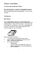
NOTICE The unit is equipped with a NiMH battery pack. It is possible that the customer might receive the battery pack in a discharged (dead) state due to product storage. This is normal. In the above situation, plug the 9V/500mA AC-DC adapter into the PT500 and an available 110V electrical outlet, switch on the PT500, and fully charge the NiMH battery pack for 14-16 hours. Or place the PT500 into the optional charging cradle for 3 hours before using the unit.
Table of Content Page Chapter 1 1.1 1.2 1.3 Overview…...………………………… Technical Specification……………… Software System…………………….. Application Development……………. Chapter 2 Installation 2.1 2.2 2.3 2.4 2.5 2.6 Chapter 3 3.1 3.2 3.3 3.4 1 2 2 2 Power On and Off the PT-500……… Batteries………………………………. Main Battery………………………….. Backup Battery………………………. Using the Keypad…………………… Triggering the Scanner Module……. Interface Port………………………… Optional Charging Cradle………….. 3 3 3 4 5 6 6 8 Operation………………………..
Chapter 1 Overview The PT-500 Portable Data Terminal with built-in barcode scanner is a rugged, compact and lightweight hand-held terminal designed for data collection. It offers many features for efficient barcode reading, keyboard data entry, and data processing. It is ideal for a wide range of Automatic Data Collection situations such as transportation, warehouse distribution, retail management, asset tracking, and many other applications.
1.1 Technical Specification ?? ?? ?? ?? ?? ?? ?? ?? ?? ?? ?? ?? ?? ?? 8-bit microprocessor CPU. 64KB ROM. 256KB, 512KB, or 1024KB RAM memory. 32x122 dots graphic LCD, 4 lines x 20 characters. Low power consumption. Standby 25mA Active 160mA Rechargeable NiMH or 3 disposable AA size alkaline batteries. Rechargeable Lithium backup battery. Real time clock. 36 keys alphanumeric rubber keypad. Optional integrated laser/CCD scanner. One good read LED indicator to scanner input. One standard RS-232 port.
Chapter 2 Installation 2.1 Power On and Off the PT-500 Press the Power Key ? located near the bottom left corner to turn the terminal on and off. As a safeguard, the unit can only be turned off by pressing the power key ? for at least 3 seconds. 2.2 Batteries Main Battery The PT-500 operates with either a rechargeable nickel metal-hydride (NiMH) battery pack or three standard AA size alkaline batteries. When the main battery is running low, the LCD display will start blinking.
4. 5. Insert the batteries in the positions as shown by the polarity symbols inside compartment Replace the battery cover and move the latch back to the locked (centered) position. If you are using NiMH battery pack, please charge the NiMH batteries continuously for 14 to 16 hours with AC-DC power adapter, or 3 hours with the optional charging and communication cradle. Note: The AC-DC power adapter is only for NiMH battery pack recharging. It won’t recharge alkaline batteries.
When the PT-500 is switched on and the Lithium battery is discharged, the following low backup battery warning message will be displayed on the PT-500 LCD: BACKUP BATTERY LOW! In this situation you should upload your data from the PT500 to a PC and have the Lithium battery replaced. Contact your local sales or service representative for replacement of the Lithium battery. Note: Data may not be backed up and data loss may occur if both the main battery and the Lithium battery are discharged. 2.
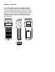
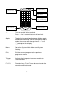
Exit key to previous menu Exit Menu 1 A 2 B 3 C Enter (YES) 4 D 5 E 6 F Bksp 7 G 8 H 9 = 0 K . - ?? ,? Del Q Ins R J + M * N / O % Power key to turn On & Off. P $ I L # SP (NO) Caps Go to system menu and select setting Integrated scanner trigger button Switch to upper & lower case letter input Edit S T U F1 W F2 X F3 Y V F4 Z Alpha Unitech Switch between Alpha & Numerical keys ? Turn on and off of the terminal. Press ? for 3 seconds to turn off terminal.
2.4 Triggering the Scanner Module The PT-500 can be used with a built-in integrated laser or CCD scanner module. To use the scanner, just point the scanner window at a barcode and press the trigger that activates the scanner. A short beep from the buzzer and flashing red LED indicator on top of the LCD display indicates when the scanning is successful. 2.5 Interface Port The PT-500 includes a DSUB-9 pin male connector, located at the base of the terminal, for serial communication with a PC.
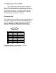
RS232 cable Exit Menu 1 A 2 B 3 C D 7 G 5 E 8 H 6 F 9 0 K . - ?? ,? Del Q Ins R 4 = J + M * Bksp SP I L (NO) MODEM Caps N / O P % S $ F1 F2 W Enter (YES) # T Edit U F3 X Y V F4 Z Alpha Unitech TELEPHONE LINE MODEM COMPUTER SYSTEM RS-232 PORT 2.6 Optional Charging and Communication Cradle The PT015 is an optional charging and communication cradle (docking station) designed to work with the PT-500.
SPARE COMM MAIN RS232 POWER ON OFF DC9V BACK FRONT PT015 RS485 RS232 RS485 SIDE BOTTOM The cradle also provides selectable data communication to the host computer - either point-to-point RS-232 or multipoint RS485 connection. The following diagram shows how the cradle works with the PT-500.
POINT-TO-POINT RS232 Connection Exit Menu 1 A 2 B 3 4 D 5 E 6 7 G 8 H 9 = 0 K .
MAIN Indicates the charging status of the main battery installed in the PT-500. The glowing Red LED indicates charging is in progress. The glowing Green LED indicates charging is complete. POWER When the power is turned on, the glowing Green LED indicates the cradle is ready to use.
Chapter 3 Operation The operating system of the PT-500 has 4 different operating modes for different purposes and functions. They are as follows: 1. Ready Mode. ?? Keypad Input will be displayed on the LCD and sent out though RS232 port. ?? Laser or CCD Scanner Input will be displayed on the LCD and sent out through RS232 port. ?? RS232 Input will be displayed on the LCD. 2. System Mode. ?? Menu will guide you to configure and diagnose the system. ?? Multi-point protocol is enabled.
?? The PT-500 can execute user-developed applications under Application Mode. Applications will share the configuration settings and files of the system. After the execution of an application, the PT-500 returns to the Ready Mode. The following sections will guide you through the operation functions and features of the PT-500. They include descriptions and charts to help you operate your terminal. 3.
(This example is for units with 1024KB RAM memory. Units with 128, 256, or 512 KB memory will display messages appropriate for their respective memory size.) Hold the power on/off key down for at least 3 seconds. The PT-500 will shut down. Release the power on/off key and press it again to power on. You should see the display return to the Ready Mode. Under the Ready Mode, your keypad input will be displayed and sent out through the RS232 port.
3.2 System Mode MAIN MENU System Mode is the main window to access other system functions and settings. Simply press the [MENU] button on the right-hand top corner under Ready Mode to change to the System Mode display. < MAIN 1-RUN 3-DIR 5-DIAG MENU > 2-SET 4-DEL 6-INIT The Main Menu has six selections from which to choose. Under the System Mode, Auto Power Off feature is always disabled, and the Multi-Point Communication Protocol is enabled unless specified.
terminal. MAIN.EXE is a user application program downloaded to the PT-500. MAIN.EXE and its internal name (Song Demo v1.00, which is defined in the RESOURCE area of user’s C program) will appear only if you have downloaded the program into the PT-500. EzJob features will be described in more detail in the EzJob Mode section. In this example: Select [1] to run EzJob. Select [2] to run MAIN.EXE. Select [EXIT] to return to the previous menu. 2.
Select [1] to change the time < TIME MENU > TIME 00:00:00 XX:XX:XX Enter the correct time (HH:MM:SS). Press [Enter] to save and exit to previous menu. Press [EXIT] to abort and exit to previous menu. Select [2] to change the date < DATE MENU > DATE 00/00/2001 XX/XX/XXXX Enter the correct date (MM/DD/YYYY). Press [Enter] to save and exit to previous menu. Press [EXIT] to abort and exit to previous menu. 2. CODE MENU Select [2-CODE] to enable/disable the barcode symbologies decoding.
3. COMM MENU Select [3-COMM] to change the settings of the RS232 port. < COMM MENU > Baud Rate 9600 Press [SP] to change the setting. Press [Enter] to confirm the setting and continue to the next selection. Press [EXIT] to abort the last change and exit to the previous menu. 4. BEEP MENU Select [4-BEEP] to adjust the volume of the beep. < BEEP 1-None 3-Med MENU > 2-Low 4-Hi Press digit 1 to 4 to select your beep volume. Press [Enter] to test the selected volume.
There are four user-definable function keys, F1 to F4. Under Ready Mode, pressing one of them will automatically perform a series of keypad inputs. The default settings for the function keys are: F1 F2 F3 F4 [MENU]111 [MENU]22 [MENU]23 [MENU]26 For example, pressing F1 under the Ready Mode, will perform the same as if you were to press the four keys [MENU] 1 1 1 sequentially. In this case, EzJob will start and will accept data input.
Use F3 or F4 to either abort or confirm the settings and then return to the previous menu. 6. MISC MENU Select [6-MISC] to modify Power Auto Features. < MISC MENU > 1 - Auto PowerOff 2 - Auto Run Select [1] to change Auto PowerOff feature. Select [2] to change Auto Run program. Select [Exit] to return to the previous menu. 1. Auto Power Off < MISC MENU Auto PowerOff > ON Press [SP] to change the setting. Press [Enter] to confirm the setting.
Press [SP] to select the auto run program from start up. Press [Enter] to save the setting and return to the previous menu. Press [EXIT] to abort and return to the previous menu. 3. DIR MENU Select [3-DIR] to list files. Files can be data, fonts, or an executable program saved in the PT-500. < DIR MENU > EZJOB TAB 1056 Byte(s) 2-Next Press [1] to scroll backward. Press [2] to move forward. Press [EXIT] to exit to the previous menu. 4. DEL MENU Select [4-DEL] to delete files from the PT-500.
Press [EXIT] to exit to the previous menu. 5. DIAG MENU Select [5-DIAG] to diagnose the PT-500 to determine if there are any hardware problems. < DIAG 1-LCD 3-COM MENU > 2-KBD 4-MEM Select [1] to diagnose LCD Select [2] to diagnose Keypad Select [3] to diagnose RS232 port Select [4] to diagnose Memory Select [Exit] to return to the previous menu Note: Multi-Point Protocol will be disabled temporally while the system is diagnosing itself. 1.
3. DIAG COM < DIAG MENU > Connect Pin 2-3, 7-8 Ready? (Y/N) Before diagnosing, loop back the RS232 port Pin 2-3, Pin 7-8, and press [ENTER]. The test result will be displayed on the bottom line. 4. DIAG MEM < DIAG MENU Bank: 00 Offset: F800 > During diagnosis, Memory Bank and Offset values will be displayed. If no problem is encountered, a “PASS” message will be displayed and you can exit to the previous menu. If a problem is found, a warning message will ask whether the test should be aborted.
Note: Initialization will remove any data and user programs from memory. Please upload any important data and then press [YES] to confirm or [NO] to abort. Select [EXIT] to return to Ready Mode. 3.3 EasyJob Mode Easy Job is an application generator to help the user to define simple data collection tasks for the PT-500. The EzJob Menu consists of 4 selections for different functions and settings.
Left-arrow, right-arrow, and backspace keys can be used for editing. Prompt 1 ???????????????????? ???????????????????? During data input, the user can browse the input data, insert one new record, or delete one existing record. In order to edit data, press [EDIT] under the INPUT prompt, use the arrow keys to move forward or backward, press [INS] to insert one new record, or press [DEL] to delete one existing record. Note: One record may consist of more than one field of data.
Purge Data can be used to delete all the data records after uploading data to the PC. The PURGE feature will delete all the data records but still retain the data format. Purge 30 Sure? (Y/N) Press [YES] to confirm or [NO] to abort. The second line number is the number of data records currently in memory. A beep will sound after the purge is completed. 4. FORMAT The FORMAT feature defines the data collection input format.
If ON, the EOF (1A Hex) will be sent at the end of the data record. Field Delimiter Record Delimiter Delay , / ; /SPACE/NONE The Field Delimiter will be used to separate the fields in each record. CRLF/NONE/CR/LF The Record Delimiter will be used to separate the records in one file. 0 to 9999 ms Time delay between the output of each record.
If ON, each record will include a time stamp automatically following the data record. The time stamp format will follow the setting defined by Time Style. 1 to 16 Data input fields are numbered 1 through 16 (maximum). Each field will have its own Prompt, Picture, Min, and Max. Prompt will display the message prompting data input. Picture is a sequence of characters that verifies the data format. Min is the minimum length of the field. Max is the maximum length of the field.
x Printable characters. (ASCII code 32 - 126) Full ASCII characters. Control character used to append constant string. This character can appear only at the beginning of a picture. z % Min >=1, <=Max Minimum length of data input. Max >=Min, <=40 Maximum length of data input. Note: Bold characters represent the default setting for each parameter. 3.4 Application Mode Advanced users can create custom programs for the PT-500 by using the C programming language.
MAININFO COM SETENV BAT ASM BAT C51 BAT LNK BAT H
C R03 S03 XCL APP LST MAP Converter Set the environment Assembly Compiler Linker C Header files C Source files Object & Lib files Assembly files Cross files C-Source files List files Map files The following steps illustrate how to create an application under the MS-DOS operating system: 1. Select PT500 as the current directory. 2. Type SETENV to set the environment. 3. Create a project file called APP.