USER’S GUIDE PORTABLE DATA COLLECTION TERMINAL PT600 DOCUMENT NUMBER: 350600-0010
NOTICE The unit is equipped with a NiMH battery pack, however it may not be powered on due to discharging of the battery by putting in storage for a period of time. In the case of above situation happened, plug in an 9V AC-DC adapter and recharge the NiMH battery pack about 14~16 hours or put into cradle about 2.5 hours with 12V AC-DC adapter before using the unit. (please refer to chapter 2.
Table of Content Chapter 1 1.1 1.2 1.3 1.4 1.5 1.6 Chapter 2 2.1 2.2 2.3 2.4 2.5 Chapter 3 3.1 3.2 3.3 3.4 Chapter 4 4.1 4.2 4.3 4.4 Page Introduction .......................................... 1 Technical Specification ................................ Interface Ports ............................................. Using the Keyboard ..................................... Triggering Scanner Module.......................... Application Development Environment ........ Optional Charging/Communication Cradle.
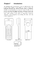
Chapter 1 Introduction The PT600 Portable Data Terminal, referred as PDT hereafter, with integrated laser scanner or pen scanner is a rugged, compact and lightweight hand-held data collection terminal with good reliability, flexibility and maintainability. Its compact size and form makes it even fits in your packet. The PDT incorporates a DOS-based system and provides users a PC compatible environment to develop and use the device.
1.1 Technical Specification SOFTWARE PROGRAMMING TOOLS Language Assembly, C language (MSC, Turbo C, Visual C) JobGen Plus A Windows-based transaction program generator JobGen Pro A Dos-based transaction program generator FormCaching A built-in program generator CPU/MEMORY CPU 16-bit 8088 compatible microprocessor CPU Memory 512KB to up of 4.
COMMUNICATION Interface One EIA RS232C with miniature DIN-9p male connector, Support TX/RX, CTS/RTS, GND, up to 57.6Kbps (default value is 19.2 Kbps) One IR port, Support TX/RX, from 19.2 to 57.6 Kbps Handshaking Xon/Xoff or CTS/RTS Protocol None or Multi-protocol File Transfer Build-in Kermit server or Multi-protocol POWER SUPPLY Operation 2AA size NiMH @ 1.
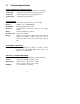
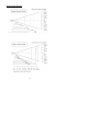
• Built-in power-on self test and diagnostic program • Host command remote control Integrated Laser Diode Scanner • Scan rate • Skew Tolerance • Pitch Angle • Power consumption 36 scans/sec ±65° from normal ±55° of normal 60mA typ.@5V Integrated clip-on Pen Scanner • Resolution 0.12mm(5mil) • Dept of field 0.1mm(0.04inch) • Scan rate 5-200 cm/sec • Reading Angle 45° ~ 135° • Print Contrast Ratio 0.
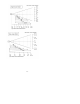
Depth of Field diagram -5-
-6-
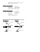
Diagram shown with a clip-on pen scanner 45° 45° -7-
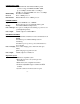
1.2 Interface Ports The PT600 has a RS232C serial port with miniature RJ10 connector, Communication by Infrared LED which on the left side of lower cabinet and charging pads locate on the bottom. Pin Signal Direction Description 1 DC9 V Input External power input 2 TXD Output Transmit date 3 RXD Input Receive date 4 N.C. 5 GND Reference Ground 6 N.C. 7 CTS Input Clear to send 8 RTS Output Request to send 9 N.C. 10 N.C. 1 10 The diagram below shows the way to connect input/output devices to the PDT.
1.3 Using the Keyboard The keypad of PT600 consists of 27 rubber keys, the key is used to switch on/off the unit and other 26 keys are used to control the unit and key in data. The use of keyboard is categorized to three modes: normal mode, command mode, and alpha(betic) mode. All keys except key may produce a sound (tone) when pressed. Keys of upper four rows have larger size for easier key-pressing to input numbers. [ ] When the unit is off, pressing the key will turn on the unit.
NORMAL mode Keyboard of the PT600 is initialized to normal mode after powered on. In normal mode, the cursor is a block sign and the keyboard is mainly used to input numeric data and use F1-F4 four function-keys. The keypad layout of available keys in normal mode is shown on right picture. Enter key for next data search Clear key for last data search COMMAND mode Press [CMD] key sets the keyboard to command mode.
ALPHA mode Press [ALPHA] key to toggle between normal mode and alpha mode of keyboard. In alpha mode, the cursor is an underscore sign and the keyboard is available to input upper case letters. In alpha mode, every numeric key contains 3 characters individually. Pressing the key [è]and [ç] to choose among three available characters. For example : First press [ALPHA] to switch the system to alpha mode, the cursor type will be changed from block to underscore To enter ‘A’, hit [ç] then [7].
1.5 Application Development Environment The system of PT600 provides DOS functions and device drivers for application development, including bar code decoding, keypad input, display output, serial input/output communication, real-time-clock access and power management control. The PT600 can be programmed by the high-level Windows-based JobGen Plus and DOS-based JobGen Pro program generation software. It can also be programmed by commonly used C compilers including Microsoft C, Borland C and Turbo C.
1.6 Optional Charging/Communication Cradle An optional charging/communication cradle (docking station), PT016, gives users a convenient accessory for daily use of the PT600. The cradle has been incorporated a quick charge circuit that the NiMH battery pack installed in the unit along with an extra spare pack can be fully charged in about 2.5 hours. Regular charging time of the battery pack through DC power adapter is about 14~16 hours.
Chapter 2 2.1 Power System Power Supply Main Power The PDT is operated by a rechargeable NiMH battery pack with two AA size 1.2V 1500mAH capacity or two AA alkaline batteries for the main power source. Back up Power An onboard 3V 190mAH Lithium battery (CR2032) is used as the secondary power source to back up the data in RTC (real time clock chip) and RAM memory to provide users a data-loss free environment.
When the main battery low condition occurs, the main battery can continue to supply power for about 10 ~ 30 minutes, however the unit may reach the system power cutoff point and automatically turn itself off. Meanwhile the unit continues to back-up the data contents in RTC and RAM, but it cannot be powered up until the batteries have been recharged or replaced.
Remove battery pack Remove backup battery Use nipper to pick up cover from screw holes for battery change. Before change Lithium battery. Note : backup Your data first. Lithium Back up Battery 1. Refer to the procedure in previous paragraph, un-screw the backup battery cover and as illustration above to remove the lithium battery. 2. Insert a new battery into the holder with correct orientation. 3. Put the battery cover back.
2.4 Recharging the Battery Pack When the PDT shows “Main battery low” message or sign , the battery pack in PDT needs to be recharged. There are two ways to charge the battery: regular and quick charging as shown below. Regular Charging Outer shell Negative(-) Inner shell Positive(+) AC to 9V DC Transformer Plug one end of an AC-9VDC power adapter into the DC-jack of RS232 cable and the other end into a wall outlet. The battery pack will be fully recharged after 14~16 hours.
Charging Considerations It is important to consider the surrounding temperature whenever you are charging the NiMH battery pack. The process is most efficient at normal room temperature or slightly cooler. It is essential that you charge batteries within the stated range of 32°F to 113°F (0°C to 45°C). Charging batteries outside of the specified range could damage the batteries and shorten their life cycle.
Chapter 3 Operation The system of PDT may operate in various modes for different purposes. The figure below shows the operating flow of the PDT. press and hold down CMD and <− keys then press PWR OFF press PWR enter program name then press ENTER APPLICATION mode PT600 V1.00 MEM 512KB > press CMD (for two seconds) RUN command press press EXIT 2 <> 1.SUPERVISOR 2.WARM START 3.COLD START press 1 then 1.RUN 3.COM 5.ERA 7.CPY 2.TER 4.DIR 6.TYP 8.
Ready mode prompt PT600 Vx.xx MEM 4608 KB > The first line indicates the model code and version number (e.g. V1.00). The second line shows the size of the total installed RAM (i.e. 4608 KB). The third line prompts a ">" which indicates that the terminal passed the Power-on-test and is ready to be used. 3.2 User Mode and System Commands There are eight system commands: RUN, TER, COM, DIR, ERA, TYP, CPY, and SET. Each command can be invoked through menu-selection in User mode.
from a Host computer. In this mode, data input from bar code reader or keyboard is displayed on screen and output to RS-232 port. Data received from the serial port is displayed on the LCD screen. Communication parameters, such as baud rate, data bits, parity, stop bits and flow control, must be set to be compatible with the destination in order to send data properly. COM This command puts the PDT in Kermit server mode.
TYP This command dumps the content of a < TYPE FILE > file on the PDT's LCD. The content of the file will be displayed 128 (16 SCAN.DAT character x 8 line) characters at a time. Press any key to show the next page or hit [CMD] then [ALPHA] keys to return to User mode prompt. If you try to display a program or binary file, you may only see unintelligible characters. CPY This command allows users to make copy of data from a source device to a destination device.
1. DATE & TIME: set system clock/calendar When selects “1.DATE & TIME” in SET DATE-TIME SETUP command menu, the screen as right will be 1998/01/01 shown on PDT’s LCD and let you set the 08:00:00 system date and time of Real Time Clock chip (RTC). The system date and time can be retrieved in application and used as time stamp for data collection. The second line shows the current date in the format YYYY/MM/DD (year/month/day).
3.4 Upload/Download by ESC Command The way to make file upload/download by Kermit server described in section 3.2 will need the operator to set the PDT to Kermit server mode by invoking user command “3.COM” in User mode or calling system function in application program. The hardware and software of PDT is designed that the unit can be waken up (turned on) by input from serial port.
Chapter 4 Built-in Application: FormCaching The system of PDT includes a built-in application, FormCaching, that allows user to create a data entry application by specifying field prompt, type, length, input method and delimiter,...,etc. without writing program and loading to the terminal. 4.1 Specification of FormCaching DATA FIELD DEFINITION: maximum field number=8 Category 1 FIELD PROMPT 2 MIN/MAX DATA LENGTH 3 DATA TYPE Range Description max.
4.2 How to Create a FormCaching You will need to enter Supervisor mode and FORM CACHING select “4.FORM” category in order to set the 1:YES configuration of FormCaching (refer to the 2:NO PT600 Programming Reference Manual for OTHER:EXIT how to enter the Supervisor mode). After selecting the “4.FORM” in Supervisor mode, the screen will show as above.
After collecting data, the FORM.DAT file can be uploaded to host either by invoking kermit server in User mode described in section 3.2 or remote ESC command described in 3.4. 4.4 Default Setting of FormCaching In default, the FormCaching is initialized with settings as shown in the table below.
Warning This is a Class A product in a domestic environment this product may cause radio interference in which case the user may be required to take adequate measures.