
Installation Instructions


to the BCM bottom plate. Otherwise, the sensitivity of the RKE will be affected. If the
installation position is determined, Changes must be confirmed with the UESA
engineer. If other materials are used, the customer must ensure that the BCM meets
the requirements for vibration, heat dissipation, temperature, and EMC. If there is
any deviation, it must be confirmed with UAES.
6.7 Distance from other sources of electronic noise
The fixed position of the BCM and its harness should be kept away from known
sources of serious electronic noise. Such as electric motors, ignition coils, high
voltage ignition lines, spark plugs, fuel injectors and generators and their wires.
7 Assembly and use
7.1 Assembly of BCM and its connectors
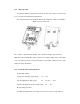
7.1.1 BCM assembly
BCM recommends the installation method of UAES design. If the customer adopts other
schemes, it must obtain the consent of UAES.
7.1.2 BCM harness connector
The BCM connector has a function to prevent insertion errors to prevent the harness
from being inserted incorrectly.
All mating terminals of the BCM end harness connector must use the terminal block
corresponding to the harness connector type defined by the customer's drawing.
The customer ensures that the external force on the BCM end harness connector
does not exceed twice the normal connector insertion force of 75N.
CAN should be twisted pair processing, otherwise the CAN signal is susceptible to
interference.
Twisted pair is required for all antenna harnesses.
The length of the PEPS antenna harness (after twisted pair processing) does not
exceed 3 meters.
IMMO backup start antenna harness length (after twisted pair processing) does not