Models: 1537M 1557M OWNERS MANUAL SOLID FUEL WARM AIR FURNACE • FOR PARALLEL INSTALLATION WITH EXISTING FORCED AIR-GAS OR OIL FIRED FURNACE. • FOR INSTALLATION AS A CENTRAL FURNACE • THE HOTBLAST FURNACE HAS BEEN APPROVED FOR U.S. INSTALLATIONS ONLY. IMPROPER INSTALLATION MAY VOID YOUR WARRANTY USSC COMPANY DO NOT USE THIS FURNACE IN A MOBILE HOME OR TRAILER UNITED STATES STOVE COMPANY 227 Industrial Park Road P.O.
CONGRATULATIONS! You've purchased one of America's Finest Wood and Coal Burning Furnaces. By heating with wood and coal you're helping CONSERVE AMERICA'S ENERGY! Wood is our Renewable Energy Resource. Please do your part to preserve our wood supply. Plant at least one tree each year. Future generations will thank you. NOTE: YOUR UNIT MUST BE INSTALLED BY A QUALIFIED FURNACE INSTALLER.
CAUTION LABELS Your Furnace has the following labels. Read and Obey all labels. DANGER: RISK OF FIRE OR EXPLOSION. DO NOT burn garbage, gasoline, drain oil, or other flammable liquids. WARNING: FIRE HAZARD. DO NOT operate with fire draft exceeding .06 inches w.c. DO NOT operate with fuel loading or ash removal doors open. DO NOT store fuels, paints, thinners, flammable liquids, or other highly volatile substances in the furnace room. CAUTION: HOT SURFACES Keep children away. Do not touch during operation.
RULES FOR SAFE INSTALLATION AND OPERATION Read these rules and the instructions carefully. Failure to follow them will cause a hazard that could result in death, serious bodily injury, and/or property damage. 1. Check your local codes. The installation must comply with their rulings. 2. Do not install this furnace in a mobile home or trailer. 3. Always connect this furnace to a chimney and vent to the outside. Never vent to another room or inside a building. 4.
HOW THE FURNACE FUNCTIONS PARALLEL INSTALLATION: (U.S. ONLY) (See Optional Wiring Diagram, Page 13, Fig. 14) The design is such that when the blower comes on, the blower on the central system also comes on. The blower will only come on when the temperature in the plenum has reached the setting on the blower control. This is to insure that there is sufficient warm air in the system to make it efficient for the unit to operate.
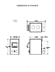
DIMENSIONS OF FURNACE FIGURE 1 1537M 6
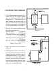
LOCATING THE FURNACE 1. The furnace should be located in the same room as the central system and as close as possible, but not closer than 9". There should be no wall between the furnace and the warm air outlet duct that is connected directly to the warm air outlet plenum of the central furnace. (See Fig. 2) 2. The unit will require installation with the following clearances: Unit to sidewall...............12"(305mm) Unit to backwall............30"(760mm) Chimney connector pipe to sidewall .................
CHIMNEY CONNECTION Fig. 4 MASONRY CHIMNEY Before using an existing masonry chimney, clean the chimney and inspect the flue liner to be sure it is safe to use. Make repairs before attaching the furnace. See page 4, item 5. Look at Fig. 4. The connector pipe and fittings you will need to connect directly to a masonry chimney are shown. The chimney connection should be as short as possible.
RULES FOR CONNECTOR PIPE INSTALLATION 1. The crimped end of the chimney connector fits inside the furnace flue collar. Install additional chimney connectors and elbow with the CRIMPED END TOWARD THE FURNACE. This will allow any condensation in the flue to run back into the furnace. Use 6" dia. steel pipe and elbows for connection to chimney. Never use less than 24 gauge and although blued steel is satisfactory, high temp painted black is much more desirable. 2.
ASSEMBLY OF FURNACE Your furnace requires the following items to be assembled or installed by the service person: Feed Door Pull Handle Feed Door Locking Handle Blower(s) and Blower Controls Electrical Connections 1. 2. 3. 4. 5. 6. 7. 8. Factory Installed Remove all parts from inside the furnace and inspect for damage, including the firebrick as some breakage could occur during shipment. Assemble the feed door pull handle as shown in Figure 8.
FIGURE 11 11
INSTALLATION Pipe to combustible: Sides: 21" Back: 18" The installation must be made only on a noncombustible floor. d) Install the smoke pipe connector to the chimney with 26-gauge pipe and elbows (to be purchased separately), maintaining the proper clearances for the specific model. Seal the smoke pipe in the chimney with furnace cement. (The chimney connector shall be securely supported, and joints fastened with sheet metal screws or rivets.
PLENUM TO CEILING 6" MIN. 2" MIN. AIR SPACE REQUIRED BY CODE PLENUM Figure 12 CENTRAL FURNACE TO GAS/OIL/ELECTRIC TRANSFORMER AND COMBUSTION FAN OF SOLID FUEL UNIT Figure 13 COMBINATION CONTROL LIMIT H POWER SUPPLY JUMPER IN N FAN GAS/OIL/ELECTRIC POWER SUPPLY JUNCTION BOX CAUTION! DO NOT CONNECT PLENUM FAN CONTROL SWITCH ACROSS FURNACE LIMIT CONTROL. FURNACE BLOWER MOTOR POWER FAILURE INSTRUCTIONS: Operation after loss of power-1. Remove filter if provided 2.
CAUTION GASES THAT ARE DRIVEN FROM FRESH COAL MUST BE BURNED OR THEY WILL ACCUMULATE AND EXPLODE. NEVER SMOTHER A FIRE WHEN ADDING FRESH COAL. OPERATING INSTRUCTIONS FUEL, Model 1537M A) Egg size (1-3/16" or larger) bituminous coal for residential furnaces, or any of the specially packed fireplace coals can be used. Coal with a low ash content (2% to 6%) is recommended. CAUTION DO NOT OPERATE WITH THE FEED AND/OR ASH DOOR OPEN. THIS FURNACE IS DESIGNED FOR THERMOSTATIC OPERATION.
SERVICE HINTS Do not expect a furnace to draw. It is the chimney that creates the draft. Smoke spillage into the house or excessive build-up of water or creosote in the chimney are warnings that the chimney is not functioning properly. Correct the problem before using furnace. Possible causes are: 4. If the chimney is operating too cool, water will condense in the chimney and run back into the furnace. Creosote formation will be rapid and may block the chimney.
MODEL 1537M REPAIR PARTS 16
. KEY 1 2 3 4 5 6 7 8 9 10 11 12 13 14 15 16 17 18 19 20 21 22 23 24 25 26 PART # 23458G 23461G 88032 40246 23459G 23457G 40258 40269 23398 40256 40257 40260 23800 83445 23787 83250 68218 23859B 891098 89574 ***** 23445 83461 83178 22662 68217 DESCRIPTION Cabinet Bottom Cabinet Side (Left & Right) Flue Collar Gasket Flue Collar Cabinet Back Cabinet Top Rear Liner Front Liner Baffle Shaker Grate Frame Shaker Grate Shaker Handle Smoke Curtain 1/4-20 x 1-1/4 Carriage Bolt Smoke Curtain Clip 1/4-20 Kep Nut A
MODEL 1557M REPAIR PARTS 18
. KEY 1 2 3 4 5 6 7 8 9 10 11 12 13 14 15 16 17 18 19 20 21 22 23 24 25 26 PART # 69509 25467G 88032 40246 23459G 25466G 40258 40269 23398 40256 40257 40260 23800 83445 23787 83250 68218 23859B 891098 89574 ***** 23445 83461 83178 22662 68217 DESCRIPTION Firebox Weldment Cabinet Side (Left & Right) Flue Collar Gasket Flue Collar Cabinet Back Cabinet Top Rear Liner Front Liner Baffle Shaker Grate Frame Shaker Grate Shaker Handle Smoke Curtain 1/4-20 x 1-1/4 Carriage Bolt Smoke Curtain Clip 1/4-20 Kep Nut
OPTIONAL 11 RPT COLD AIR DUCT 6" PIPE 90° ELBOW DAMPER PIPE CONNECTOR FURNACE FIGURE 15-1 COLD AIR DUCT 6" PIPE 8" PIPE 90° ELBOW DAMPER PIPE CONNECTOR FURNACE EXISTING GAS/OIL/ELECTRIC FURNACE FIGURE 15-1 20
APPENDIX INSTALLATION - A (U.S.
INSTALLATION - B (U.S. ONLY) TO EXISTING DUCT WORK PLENUM COLLECTOR BOX WARM AIR COLD AIR RETURN EXISTING FURNACE SOLID FUEL FURNACE FILTER BOX INSTALLATION - C (U.S.
INSTALLATION - D (U.S. ONLY) DUCT WORK 2" MINIMUIM CLEARANCE 11 PCS (OPTIONAL PLENUM FAN CONTROL LOCATION) COLD AIR RETURN FURNACE PLENUM ANTI-BACKDRAFT FLAPPER EXISTING FURNACE SOLID FUEL FURNACE INSTALLATION - E (U.S.
INSTALLATION - F 2" MINIMUM CLEARANCE COLD AIR RETURN FURNACE PLENUM EXISTING FURNACE SOLID FUEL FURNACE INSTALLATION - G DUCT WORK 2" MINIMUM CLEARANCE CENTRAL FURNACE INSTALLATION COLD AIR RETURN TO FILTER BOX SOLID FUEL FURNACE 24
INSTALLATION - H EXISTING OIL, ELECTRIC, OR GAS FURNACE SOLID FUEL FURNACE 2" MINIMUM CLEARANCE EXISTING OIL, ELECTRIC, OR GAS FURNACE SOLID FUEL FURNACE 25
Trouble Shooting Tips for Warm Air Furnace LIST OF PROBLEMS 1. Smoking when feed door is open. 2. Furnace does not heat. POSSIBLE CAUSE a) Insufficient Draft. b) Clogged chimney or chimney connector. c) Down draft in chimney. a) Wood not seasoned and dry. SOLUTIONS a) Set Thermostat higher. b) Clean Chimney. c) Add raincap to chimney. b) Insufficient flue draft. a) Allow wood to season in a dry area for six months. b) Set flue draft. (See P. 9) 3. Blower Does not run. a) b) c) d) a) b) c) d) 4.
NOTES 27
HOW TO ORDER REPAIR PARTS THIS MANUAL WILL HELP YOU OBTAIN EFFICIENT, DEPENDABLE SERVICE FROM YOUR AMERICAN HARVEST, AND ENABLE YOU TO ORDER REPAIR PARTS CORRECTLY. KEEP THIS MANUAL IN A SAFE PLACE FOR FUTURE REFERENCE. WHEN WRITING, ALWAYS GIVE THE FULL MODEL NUMBER WHICH IS ON THE NAMEPLATE ATTACHED TO THE HEATER. WHEN ORDERING REPAIR PARTS, ALWAYS GIVE THE FOLLOWING INFORMATION AS SHOWN IN THIS LIST: 1. THE PART NUMBER 2. THE PART DESCRIPTION 3. THE MODEL NUMBER: 1537M 1557M 4.