U USSC E STATES ST OV TED I N COMPANY Installation/Operator’s Manual Model: 1600EF Wood or Coal External Furnace SAFETY NOTICE: If this furnace is not properly installed, a house fire may result! For your safety, follow these installation instructions. Contact local building or fire officials about restrictions and installation requirements in your area. This furnace must be installed by a qualified technician. Keep these instructions for future reference.
UNIT DIMENSIONS 29-1/2” 2-9/16” 55-5/8” 5-3/16” 45-3/4” 65-1/2” D-RINGS FOR GUY WIRE ATTACHMENT Blower Speed Selector Switch 6” FLUE GAS OUTLET 17-5/16” 24-1/4” 29-3/16” 43-7/16” 14-1/4” Limit Switch Access 10” HOT AIR OUTLET 12” COLD AIR RETURN HOT WATER COIL ACCESS (OPTIONAL) 6” 31-5/8” USSC 2
CUT HERE " WARRANTY INFORMATION CARD Name__________________________________________ Telephone #: (_____)_____________ City____________________________________________ State_______ Zip_________________ Email Address __________________________________________________________________ Model # of Unit________________________________ Serial #___________________________ Fuel Type: qWood qCoal qPellet qGas qOther _________________________ Place of Purchase (Retailer)___________________________________________
CUT HERE " Fold Here Fold Here É United States Stove Company P.O.
INTRODUCTION GENERAL INFORMATION Thank You for your purchase of a U.S. Stove Wood/Coal Burning External Furnace. Your decision to buy our Clayton Furnace was undoubtedly reached after much careful thought and consideration. We are very proud you chose this furnace and trust you will receive the comfort and economy that others realize when heating with a U.S. Stove product. Your 1600EF furnace comes ready for installation. No assembly required.
WOOD SUPPLY FLUE PIPE INSTALLATION Some important rules for preparing good firewood are: Cut, split and stack the wood in the early spring and let it stand in the sun and wind all summer. Clearances to combustible materials will vary with the type of flue connection used. Be sure to maintain the specified clearances for your type of installation.
CONNECTING HOT AIR DUCT TO FURNACE We strongly recommend that the hot air duct work be installed by a home heating specialist. If doing the installation yourself, before you decide which installation will best suit your needs, consult a qualified heating technician and follow his recommendations as to the safest and most efficient method of installation. The warm-air supply-duct system shall be constructed of metal in accordance with NFPA 90B, 2-1.1.
TYPES OF INSTALLATION continued... CENTRAL DUCT CONNECTION When connecting to a central duct system, avoid 90 degree elbows as this will reduce air flow delivery. A duct run in excess of 40 feet is NOT RECOMMENDED. The air flow and heat output will be greatly decreased. INSTALLATION #2 The baffle on this system should be made the full width of the furnace plenum in order to properly direct the air into the distribution ducts.
FURNACE ASSEMBLY INSTRUCTIONS Read and follow these instructions in the event you have SHAKER GRATE HANDLE to replace or re-assemble components of your furnace. DOOR HANDLES Insert door handle into door. From rear side of door, place a 1/2” washer over the threaded part of the handle, then attach the lock nut. Tighten the nut, then back off 1/4 turn to allow free operation of the handle. Follow these same directions for the ash door handle assembly.
DISTRIBUTION BLOWER & ACC. A All electrical connections should be done by a qualified electrician. 1. To replace the Honeywell Limit Control (A): Unplug from power supply The control may be removable thru the access panel on item “B”. However it may be easier to remove item “B” entirely for better access. Remove item “B” by means of the eight(8) screws. If siliconed, use a utility knife to score the silicone along the edges of the part.
MOTORIZED NATURAL DRAFT REPLACEMENT 1. Make certain the unit has been unplugged from the power source. Remove the cover from the motor and remove the two wire nuts and grounding screw. With a pair of pliers, remove the strain relief and cord assembly from the motor. 2. Remove the draft assembly from the furnace by loosening the two bolts retaining draw band. If motor comes with the cord, the above step is not required.
TESTING AND OPERATING PROCEDURES 4. Load the furnace, close the load door and push the slide GENERAL FURNACE OPERATION After installation of the furnace is complete, it is ready for operation. The Honeywell Limit Control, in conjunction with a wall thermostat, operates the distribution blowers and the motorized draft on the front of the furnace. The limit control is located on the rear of the furnace in the upper left corner and is accessible by removing the two screws in the cover plate.
If the fire goes out or does not hold overnight, look for: 1. Poor draft. 2. Incorrect damper settings. 3. Improper firing methods for coal being used. 4. More combustion air needed. 5. Coal not sized to the furnace. We recommend 1” to 3” diameter pieces of coal. 6. Ashes, if allowed to accumulate in the ash pit, will not allow the passage of required air for combustion. Keep ash pit clean. 7. This furnace is not to be used with an automatic stoker unless so certified.
TROUBLE SHOOTING AND PROBLEM SOLVING 1. Problem: 4. Problem: Smoke puffs from furnace Distribution blower vibrating Solution: Solution: A. Check chimney draft. Check for blocked chimney or flue pipe. Use mirror to check chimney clearance. A. Tighten blower wheel to motor shaft. B. Check for bad fan bearings. B. Check ash pit — if it is too full, empty. 5. Problem: C. Make sure all of chimney mortar connections are airtight. Distribution blower continues to run or will not run D.
WIRING DIAGRAM USSC 15
PARTS DIAGRAM 16 USSC
PARTS DIAGRAM AND LIST Key Description Part # Qty Key Description Part # Qty 1 Grate Retainer 40312 2 41 Inner Top 25726 1 2 Shaker Bar 891341 1 42 Insulation, Top-Front 88150 1 3 Shaker Grate Section 40314 5 43 Insulation, Top-Middle 88151 1 4 Front Liner 40344 1 44 Insulation, Top-Rear 88152 1 5 Back Liner 40313 1 45 Mount, Flue Outlet 25727 1 6 Full Firebrick (4-1/2 wide x 9 tall x 1-1/4 thick) 89066 16 46 Weldment, Cabinet Top 69648 1 7 Half Fireb
PARTS DIAGRAMS AND LISTS - MOTORIZED DRAFT KIT 4 Key 18 Description Part # Qty 1 Weldment, Draft Tube 68872 1 2 Spin Draft 40379 1 3 3/8-16 x 2-1/2 Carriage Bolt 83503 1 4 Lock Nut, 3/8-16 83274 1 5 Actuator, Motorized Draft 80592 1 6 Tube, Flipper 23899 1 7 Flipper 23898 1 8 #8 x 1/2 Tek Screw, Hex Head 83455 2 9 Strain Relief 80154 1 10 Power Supply Cord 80593 17 in.
PARTS DIAGRAMS AND LISTS - FAN CENTER CONTROL Key USSC Description Part # Qty 1 Electrical Box Cover 25742 1 2 Electrical Box Body 25743 1 3 Switch, 3-Position 80361 1 4 Harness, 6 Circuit Receptacle 80583 1 5 Harness, 3 Circuit Receptacle 80584 1 6 Harness, 2 Circuit Receptacle 80585 1 7 Transformer, Fan Center 80130 1 8 Strain Relief 80154 1 9 Power Supply Cord 80232 1 10 #10 x 1/2 Sheet Metal Screw 83172Z 13 11 Washer, Internal tooth, #10 83240 1 19
NOTES 20 USSC
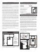
DOMESTIC HOT WATER COIL KIT - OPTIONAL This Furnace will accept the installation of a Domestic Hot Water Coil Kit. The U.S. Stove kit is a 1124 Water Coil and it may be purchased from your local dealer. 2 1. Remove the access panel on the rear of the furnace enclosure. 2. With a utility knife, cut away a section of the insulation directly behind the access panel. 1 3. Remove the cover plate from the rear of the furnace firebox. ACCESS PANEL 4.
BULLETIN RC454 A GUIDE TO BURNING COAL IN YOUR FURNACE Furnaces that are capable of burning coal usually will burn both Bituminous and Anthracite coal. Anthracite is perhaps the best coal fuel because of its long even burn time, high heat output, and cleanliness which make it a good choice for the home. However, keep in mind it is a much more difficult fuel to use, requires more care and patience, is not so widely available, and is usually much more expensive than Bituminous.
BULLETIN RC454 A GUIDE TO BURNING COAL IN YOUR FURNACE When the fire is well established and the room is becoming warm, partially close the dampers. Some experimenting will have to take place with each particular setting of all dampers and controls as the chimney provides the draft necessary to not only exhaust the smoke, but to pull combustion air into the heater as well - and no two chimney’s perform the same.
HOW TO ORDER REPAIR PARTS This manual will help you obtain efficient, dependable service from the furnace, and enable you to order repair parts correctly. Keep this manual in a safe place for future reference. When placing an order or for warranty claims, please provide the following information found on the Certification Plate located inside the cabinet door. PART NUMBER PART DESCRIPTION MODEL NUMBER______________ SERIAL NUMBER______________ United States Stove Company 227 Industrial Park Road P.O.