Wood & Coal Burning Furnace Owners Manual Models: 24A, 30A TESTED TO UL 391 All installations must be made in accordance with local and state codes which may differ from this manual. UNITED STATES STOVE COMPANY 227 Industrial Park Road P.O.
CHIMNEY INSTALLATION OVER FIRING Your new furnace must be installed into a "Class A" Chimney only. This type of chimney consists of a flue lined brick chimney, or an approved "Class A" all fuel factory built (prefabricated) type. Any other installation guarantees an immediate fire hazard. This generally occurs when the following procedures are not followed, ash door is open (even partially open), the feed door pressure relief flap is open, the feed door is open or the manual draft spinner is open.
WELCOME ...to the world of solid fuel heating! Your new furnace has been designed and built with a high grade of materials and the strictest regard to quality. Before you start installing your new furnace, take the time to read these installation and operating instructions. We have prepared them for your benefit to save time and provide some helpful knowledge on wood and coal burning. Save the instructions for future use.
GENERAL RULES Rules for the Safe Installation and Operation of Your The furnace is designed to burn air dried wood and Furnace... coal at a predetermined firing rate. Over firing could result in damage to the heat exchanger and cause Check local codes, the installation must comply with dangerous operation. Over firing occurs when the strict conformance in regard to clearances.
HOW ... W. How Your New Furnace Works Unlike conventional heating (gas, oil, electric), wood or coal heating requires more user attention. Your furnace, with its automatic combustion air blower, alleviates the constant need for adjusting the burning rate common to other units on the market. The fire, however, must be started and subsequent fuel added by the user. Conventional heating system produce heat only when the thermostat calls for heat.
INST A L L AT I O N TA Furnace location Before you start! It is very important you check with your dealer, local fire department, or building inspector. They will be able to inform you of any state or local codes pertaining to the location and installation of your furnace. The ideal location for your furnace is centrally located in the basement. This allows for an even heat distribution by having all the duct work approximately the same length.
INST A L L AT I O N TA Your furnace is designed to be added on to existing duct work and operate either with or without another heat source such as a gas furnace. The following diagrams illustrate acceptable ways of ducting your furnace. Clearance to Combustible Materials Your Furnace has been tested to determine the SAFE clearances to combustible material. The clearances are printed on the label located on the back of the furnace. The chart on this page also states these minimum clearances.
FL UE RECOMMEND A TIONS FLUE RECOMMENDA CAUTION! Only a "Class A", all-fuel chimney intended for use with solid fuel should be used. "Class A" chimneys are those made from tile-lined masonry (brick or block) or an independent laboratory approved allfuel factory-built chimney. WHAT SIZE CHIMNEY SHOULD BE USED? The Chimney size to use is either six (6) or (8) inch round or an 8 x 8" square. If you use a rectangular chimney, the minimum area it may be is 39 square inches.
FL UE RECOMMEND A TIONS FLUE RECOMMENDA CHIMNEY INSTALLATION FACTORY-BUILT OR METAL CHIMNEYS With the chimney being the most important part to If your home has an existing metal chimney, the same rules your installation, great care should be given to its apply as with masonry chimneys. One thing to be especially aware of is that "Class B" chimneys are for gas applidesign. ances only, not solid fuel burners. If purchasing a new packMASONRY CHIMNEYS age, consult with the dealer.
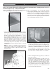
ASSEMBL Y ILL USTRA TIONS ASSEMBLY ILLUSTRA USTRATIONS NOTE: Your furnace may come partially pre-assembled, but in the case that it is not, follow the instructions below. Also use these instructions for future maintenance and disassembly. Drawings and photos are for illustration purposes only. Actual parts may differ. Prior to assembling, place the unit in the general vicinity of the installation. This should help minimize handling damage to the unit after assembly. 2. Attaching the distribution fans.
ASSEMBL Y ILL USTRA TIONS ASSEMBLY ILLUSTRA USTRATIONS 5a. Attaching furnace control center box. To separate outer cover, remove two (2) side screws and 7. Wall thermostat should be mounted on an upstairs inside wall (no outside facing wall) preferpull off black rheostat knob. Attach box to left ably near your existing thermostat. For more speside (facing feed door) with four (4) self-threadcific information, read the Honeywell instruction ing screws. One screw in each corner.
ASSEMBL Y ILL USTRA TIONS ASSEMBLY ILLUSTRA USTRATIONS CAUTION: Any hot air plenum connection to a furnace must be constructed of metal. 11. Installing Grates: Install grates together, slip shaker lug into hole and place grates into frame. Grate arch faces upward. Check out grate rotation by placing shaker handle on grate lug (3/4"). Grates 9. Installing collar to top: To install hot air attaching should rotate freely.
ASSEMBL Y ILL USTRA TIONS ASSEMBLY ILLUSTRA USTRATIONS 13. Installing front and rear cast baffles, heat plates. 15. Installing smoke damper rod to sliding smoke NOTE: Grate frames and brick will slide forward damper. First, insert rod through hole above feed and backward to allow baffle to fit. Install front door and push forward. cast baffle using two (2) 5/16 bolts, nuts & washers (7/16 wrench will be needed). Place the side of the baffle that has the two ribs against the front weld of the firebox.
ASSEMBL Y ILL USTRA TIONS ASSEMBLY ILLUSTRA USTRATIONS 17. To install Feed Door handle, insert handle into the 19. To install the dampers on the doors, screw the door then attach with the 1/2-13 nut and washer damper up onto the 1/2-13 carriage bolt proprovided. Tighten nut against the backside of vided. Then screw the damper and bolt into the the door then back it off approx. 1/4 turn or until door until the bolt protrudes the rear of the door handle moves freely.
CONTROL BO X & ELECTRICAL COMPONENT BOX 140 degree adjustable disc. (Left Dist. Blower) 170 degree limit disc 140 degree adjustable disc. (Right Dist. Blower) ELECTRICAL COMPONENTS Wall Thermostat *(2) 140 degree Adjustable Thermo Disk *(1)170 degree Thermo Limit Disk *(1)Relay Transformer (2) Air Distribution Fan (1)Draft, Fan * Control Box Components 10 BASIC FUNCTIONS OF ELECTRICAL SYSTEM Your new furnace is now completely assembled and ------- -1. 2. 3. 4. Relay...
OPERA TION AT 5. Push in bypass damper after fire has progressed. MAINTENANCE 6. Your furnace is capable of putting out many BTU's, so don't fully load your furnace until you have become familiar with the operation of the furnace. Keep in mind, a full load will not always give you the best results for your needs. Note: With new steel, there is a small amount of oil or dirt on the metal. You may smell an odor. This is normal during the first operation.
OPERA TION AT BURNING COAL Your furnace is capable of burning both Bituminous and Anthracite coal. Anthracite is perhaps the best coal fuel because its long even burn time, high heat output, and cleanliness make it a good choice for the home. However, keep in mind it is a much more difficult fuel to use, requires more care and patience, is not so widely available, and is usually much more expensive than bituminous. of the ashes without disturbing the fire.
OPERA TION AT If, however, there is no flame then the fire needs more The amount of shaking is critical. Too little or too air from the bottom (unless it is near the end of its much of both can result in the extinguishing of a fire burn cycle and needs to be recharged). due to blocked air flow. The proper amount norOnly when the coal is burned down to half its origi- mally occurs when red coals first start to drop through nal depth is it time to add fresh coal. When doing so, onto the bed of ashes.
SAFETY - OPERA TION OPERATION Whenever the loading door is opened, it should be cracked slightly (for about ten (10) seconds) to allow oxygen to enter and burn any combustible gases that are present before fully opening. Failure to do this could result in sudden ignition of the unburned gases when the door is opened. This furnace is equipped with a safety latch system to reduce the rsik of sucjh an ignition. Always wear a glove to protect you hand from the heat.
TROUBLE SHOOTING TROUBLE-SHOOTING, PROBLEM SOLVING FOR YOUR FURNACE 1. Problem: Smoke puffs from furnace. Solution: A. Check chimney draft. Check for blocked chimney or flue pipe. Use mirror to check chimney clearance. B. Check ash pit - if too full, empty. C. Make sure furnace room is not too airtight. D. Make sure all chimney mortar connections are air tight. E. Check clean out door. Make sure it's airtight. F. Check chimney for possible down-draft caused by taller surrounding trees or objects.
REP AIR P ARTS DIA GRAM REPAIR PARTS DIAGRAM USSC Page 21
Page 22 KEY PART # DESCRIPTION 1 2 3 4 5 6 7 8 9 10 11 12 13 14 15 16 17 18 19 20 21 22 23 24 25 26 27 28 29 30 N/S 31 N/S 32 33 34 35 36 37 38 39 40 41 42 43 44 45 24490 25613 24489 25614 24488 25615 69542 69559 89636 83835 83444 40379 83503 83274 891423 83045A 23786 83339 83250 23823 891135 24501 83445 23787 69543 69568 40366 24487 24496 40369 40349 40376 40350 24828 25612 83874 89066 891414 24220 C97999 89799 80496 89319 80422 69081 24492 80130 80388 80390 80090 80131 80231 LEFT CABINET SIDE LEFT C
WIRING SCHEMA TIC SCHEMATIC USSC Page 23
HOW TO ORDER REP AIR P ARTS REPAIR PARTS THIS MANUAL WILL HELP YOU OBTAIN EFFICIENT, DEPENDABLE SERVICE FROM YOUR FURNACE, AND ENABLE YOU TO ORDER REPAIR PARTS CORRECTLY. KEEP THIS MANUAL IN A SAFE PLACE FOR FUTURE REFERENCE. WHEN WRITING, ALWAYS GIVE THE FULL MODEL NUMBER WHICH IS ON THE NAMEPLATE ATTACHED TO THE HEATER. WHEN ORDERING REPAIR PARTS, ALWAYS GIVE THE FOLLOWING INFORMATION AS SHOWN IN THIS LIST: 1. THE PART NUMBER 2. THE PART DESCRIPTION 3. THE MODEL NUMBER: 24A 30A 4.