Keeping America Warm Since 1869 CORN & PELLET MULTIFUEL STOVE 6039, 6039I, 6039T OWNER’S MANUAL Installation - Operation - Maintenance Instructions - Repair Parts READ THIS ENTIRE MANUAL, THOROUGHLY, BEFORE ATTEMPTING TO INSTALL AND/OR BURN YOUR NEW AMERICAN HARVEST CORN AND PELLET MULTI-FUEL STOVE. FAILURE TO FOLLOW THESE INSTRUCTIONS MAY RESULT IN PROPERTY DAMAGE, BODILY INJURIES OR EVEN DEATH. Safety Notice: If this stove is not properly installed, a house fire may result.
CONGRATULATIONS! You've purchased one of America's Finest Multifuel Burning Stoves. By heating with fuels such as corn and pellets, you're helping CONSERVE AMERICA'S ENERGY! NOTE: YOUR UNIT MUST BE INSTALLED BY A QUALIFIED INSTALLER, such as an NFI Certified Specialist We strongly suggest installing smoke detectors in your home if not already installed. Initial burn off may cause slight smoke and odor the first few hours of operation.
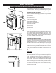
ASSEMBLY 1. The Auger is packed in the hopper or ash pan and must be installed properly as illustrated below. 2. Insert the Auger into the auger tube. Rotate the auger until it fits into the coupling that is already installed on the auger motor drive. Seat the auger firmly. The Auger cannot be turned by hand once installed properly. 6039T ASSEMBLY Assembly 1. Unpack unit and make sure all components are included; (4) Legs, and all hardware for installation. 2.
6039I ASSEMBLY DISCONNECT THE POWER CORD BEFORE SERVICING THIS STOVE For the following assemblies, we suggest locating the unit near it’s desired location. Depending on installation, you may want to connect the exhaust venting before installing the facade parts.
COMPONENT LOCATION USSC 5
SAFETY STEPS IMPORTANT: Proper installation of this stove is necessary for safe and efficient operation. Installing this product improperly may result in a house fire and personal injury. All applicable building codes for your location must be followed. In areas where building codes require additional steps to the installation of this product not included in this manual, the building codes will take precedent and must be followed.
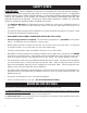
BURNING SOLID FUELS continued... SHELLED CORN (Dry, preferably corn with 11- 12% moisture content) • Corn must contain less than 14% moisture content. Wet corn will rapidly deteriorate stove components, reduce efficiency and void all warranties. Purchase a moisture tester if in doubt. • Corn must be clean and free from debris. Never burn corn right from the field. Damage caused by dirty corn is not covered by the product warranty. Ask for clean filtered bagged corn only.
CLEARANCES TO COMBUSTIBLES 6039(T) The stove must be installed with the following minimum clearances to side and back wall combustible materials. NOTE: These are minimum clearances to combustible walls established by the testing lab. PARALLEL - A BCDCORNER - Sidewall to Top Edge of Unit Sidewall to Flue Backwall to Flue Backwall to Unit 8 in./203mm 13 in./330mm 3 in./75mm 9 in./228mm E - Adjacent Wall to Flue F - Adjacent Wall to Unit 3 in./75mm 4 in.
CLEARANCES TO COMBUSTIBLES 6039I USSC 9
GUIDELINES FOR EXHAUST VENTING SYSTEMS DESIGN It is recommended that only an authorized installer install your pellet/corn stove, preferably an NFI certified specialist. The following installation guidelines must be followed to ensure conformity with both the safety listing of this stove and to local building codes. INSTALL VENT AT CLEARANCES SPECIFIED BY THE VENT MANUFACTURER.
DESIGN GUIDELINES FOR OUTSIDE COMBUSTION AIR CONNECTION 1) For installations with horizontal through-the-wall exhaust, it is strongly recommended that the stove combustion air be connected to the outside. If the home is newer or has been tightly insulated, it is required to install outside combustion air. 2) Connection to outside the house is REQUIRED for mobile home installations. We strongly urge use of the 69FAK Fresh Air Kit. 90 DEGREE BEND TERMINATION WIND HOOD TERMINATION Wind Hood 2” Min.
INSTALLATION CONFIGURATIONS Note: Where passage through a wall, or partition of combustible construction is desired, the installation shall conform to CAN/CSA -B365 The American Harvest Corn/Pellet Stove Model 6039/6039T may be installed as follows: 1) A freestanding unit The American Harvest Corn/Pellet Stove Model 6039I insert may be installed as follows: 1) In a pre-fab firebox (Factory Built) 2) In an existing masonry fireplace 3) As a build-in MOBILE HOME INSTALLATION REQUIREMENTS IN ADDITION TO THE
Note: Always check dimensions on unit before cutting hole in wall 3" PL Vent Termination Cap 3" PL Vent 90° Elbow 3" PL Vent (12" Long) 3" PL Tee w/ Cleanout 3" PL Vent (12" Long) 3" PL Vent (12" Long) Outer Wall Thimble Inner Wall Thimble 6039 - PEDESTAL UNIT EXHAUST OULET 3" DIA. 12 1/8 10 1/16 3’ Minimum Vertical Pipe 6039T - LEG UNIT COMBUSTION AIR INTAKE 1 7/8" DIA.
THROUGH THE WALL, VERTICAL PIPE INSTALLATION WITH TERMINATION CAP The Hearth Pad is not required under the unit if the floor is noncombustible but is required 6 inches (152mm) beyond the front of the unit and 6 inches (152mm) beyond each side of the door if the floor is a combustble floor. wood flooring, carpet, linoleum, etc.
DESIGN GUIDELINES FOR 6039I INSERT INSTALLATION INSTALLATION AS A BUILT-IN FIREPLACE A continuous sheet of non-combustible floor protection must be installed underneath the unit to prevent the possibility of embers falling through to the combustible floor. If the floor beneath the unit is of non-combustible material, the protector is not required. See the “Clearance to Combustibles” section of this manual for installation clearances.
DESIGN GUIDELINES FOR 6039I INSERT INSTALLATION INSTALLATION INTO A MASONRY FIREPLACE When installing into a masonry fireplace, DO NOT remove any bricks or masonry, with the following exception: masonry or steel, including the damper plate, may be removed from the smoke shelf and adjacent damper frame, if necessary, to accommodate a chimney liner.
GLASS MAINTENANCE, REMOVAL AND REPLACEMENT Your American Harvest Corn/Pellet Stove comes to you with the glass door installed in place, ready for use. The glass is surrounded on the edges with a gasket and seated in a glass channel. It is held in place with two (2) clips. REMOVAL OF BROKEN OR DAMAGED CERAMIC GLASS Open the door and lift off of hinges. If the door is tight, tap gently on the bottom of the door with your hand or rubber hammer. Lay door down on newspaper with glass clips facing you.
UNDERSTANDING THE CONTROL BOARD CONTROL PANEL Turning the heater OFF/ON, as well as adjustments for the fuel feed rate and room fan speed are performed by pressing the appropriate button(s) on the control panel which is located on the lower left-hand side of your American Harvest heater. The insert model 6039I is located on the left facade. This unit can be changed between an automatic operation or a manual operation. The controller comes default in the automatic mode.
LIGHTING INSTRUCTIONS CAUTION: DO NOT USE CHEMICALS OR FLUIDS TO START THE FIRE HOT WHILE IN OPERATION. KEEP CHILDREN, CLOTHING AND FURNITURE AWAY. CONTACT MAY CAUSE SKIN BURNS. Before lighting your heater for the first time, make sure that all items are out of the hopper, ash pan and firebox area. Press the “On” button and allow your heater to run for at least 4 minutes, to check for proper operation. Once your heater is started, you will notice the draft fan starts immediately.
DISPOSAL OF ASHES Disposal of Ashes Ashes should be placed in a metal container with a tight fitting lid. The closed container of ashes should be placed on a noncombustible floor or on the ground, well away from all combustible materials, pending final disposal. If the ashes are disposed of by burial in soil or otherwise locally dispersed, they should be retained in the closed container until all cinders have been thoroughly cooled.
Weekly Maintenance • Shut down the stove as directed in the operating instructions. Allow the stove to cool to room temperature. Remove the small clean-out slides in the lower corners of the firebox. Tap the sides of the burn chamber with a wooden stick. Do not tap the firewall behind the burn box as it may damage the insulation. Scrape the fly ash from the clean-out chambers toward the front of the burn chamber. Remove the fly ash from the burn chamber and replace the clean-outs.
CIRCUIT BOARD FUNCTIONS START-UP SEQUENCE OF EVENTS Once the control panel is turned to on, a timer begins that will start, stop and continue operation of the American Harvest as a preset temperature is achieved. COMPONENT OPERATION START OPERATION END Draft Fan Starts Immediately Will continue until shutdown. Shutdown will occur when the operating temperature is below 90 degrees.
ERROR CODES and DISPLAY INDICATORS CAUTION: When performing any internal electrical maintenance • Moving parts inside of the cabinet may cause injury. Do not operate unit with panels removed or open. • HOT parts. Do not operate the unit with panel open. • Risk of electric shock. Disconnect power before servicing unit. • In the event of component failure, replace with the original factory equipment. Error Code Error Descrption Possible Causes Err1 The high limit temperature sensor has tripped.
TROUBLE SHOOTING Unplug stove before performing any maintenance PROBLEM ? Fire burns with a lazy, orange flame and/or fuel builds up in the firepot. Glass may become dirty. CAUSE: Too rich air/fuel mixture 9 Make sure that the manual damper slide below the door is pulled out. ( in the open position ) 9 Make sure glass door is shut and sealed tightly. If not, adjust door handle or replace gasket. 9 Check that exhaust fan is running and venting properly. If not, check connection and clean or replace.
WIRING DIAGRAM USSC 25
REPAIR PARTS DIAGRAM-6039 26 USSC
FOR MODEL: 6039 REPAIR PARTS LIST-6039 USSC KEY 1 2 3 4 5 6 7 8 9 10 11 12 13 14 15 16 17 18 19 20 21 22 23 24 25 26 27 28 29 30 31 32 33 34 35 36 37 38 39 40 41 42 43 44 45 46 47 48 49 50 51 52 53 54 55 56 57 58 59 60 61 62 63 N/S PART # 69516 25080MB 25409MB 69508MB 25451MB 69478MB 891138 25493 25468MB 25471MB 25472MB 25411MB 25412MB 25413MB 25448 25447 69477MB 69503MB 891125 69499 88116 88114 69498 88100 80473 80456 83511 83533 891136 88106 80472 80507 80488 88111 83534 25422 891132 86620 83901 25427
REPAIR PARTS-6039I 23 14 15 23 25 20 24 12 13 16 21 22 19 27 26 18 1 7 6 3 4 6 17 5 28 29 2 10 10 8 9 11 28 USSC
FOR MODEL: 6039I REPAIR PARTS LIST-6039I KEY 1 2 3 4 5 6 7 8 9 10 11 12 13 14 15 16 17 18 19 20 21 22 23 24 25 26 27 28 29 PART # 891373 69547MB 25569 891424 83412 83136 83261 69548MB 891137 25570MB 83479 69549 88115 25586MB 891148 25581MB 25579MB 25580MB 25578MB 25587MB 89943 25585MB 25590MB 80507 25583MB 25582MB 891435 891135 891331 DESCRIPTION Pad, Door Hinge(Threaded) Weldment, Sub-Base Bracket, Caster Caster, Plastic 1/4-20 x 1-1/2 Hex Bolt Washer 1/4-20 Lock Nut Weldment, Ash Pan Handle, Brushed N
Parts Diagrams and Parts Lists 7 10 6 5 4 9 1 3 11 8 Parts List 2 Key 1 2 3 4 5 6 Part No. 25491 25492 83506 88112 88087 891131 Descritption Feed Door Handle, Door Roll Pin, 3/8 x 1-1/4 Gasket, 1/2” Sq. Rope Gasket, Glass (1 x 3/16) Glass Ceramic Qty. 1 1 1 5 ft 4 ft 1 Key 7 8 9 10 11 Part No. 83278 25465 25464 83202 89574 Descritption #10 Flat Washer Retainer, Bottom Glass Retainer, Top Glass Machine Screw Handle, Spring (Parts Bag) Qty. 4 1 1 4 1 Parts List Louver Assembly (Part No.
Notes USSC 31
HOW TO ORDER REPAIR PARTS THIS MANUAL WILL HELP YOU OBTAIN EFFICIENT, DEPENDABLE SERVICE FROM YOUR AMERICAN HARVEST, AND ENABLE YOU TO ORDER REPAIR PARTS CORRECTLY. KEEP THIS MANUAL IN A SAFE PLACE FOR FUTURE REFERENCE. WHEN WRITING, ALWAYS GIVE THE FULL MODEL NUMBER WHICH IS ON THE NAMEPLATE ATTACHED TO THE HEATER. WHEN ORDERING REPAIR PARTS, ALWAYS GIVE THE FOLLOWING INFORMATION AS SHOWN IN THIS LIST: 1. THE PART NUMBER 2. THE PART DESCRIPTION 3. THE MODEL NUMBER: 6039 6039I 6039T 4.