U USSC E STATES STO TED V NI UNITED STATES STOVE COMPANY “Keeping North America Warm Since 1869” COMPANY MULTI-FUEL FURNACE Owner’s Manual Ì Please read this entire manual before installation and use of this appliance. Failure to follow these instructions could result in property damage, bodily injury, or even death. Ì Contact your local building or fire officials about restrictions and installation inspection requirements in your area. Ì Save these instructions.
Table of Contents TABLE OF CONTENTS .............................................................................................. 2 SAFETY PRECAUTIONS ........................................................................................... 3 SPECIFICATIONS ...................................................................................................... 4 Heating Specifications ..................................................................................... 4 Dimensions ........................
Safety Precautions Ì IMPORTANT: Read this entire manual before installing and operating this product. Failure to do so may result in property damage, bodily injury, or even death. Proper installation of this furnace is crucial for safe and efficient operation. Ì Install vent at clearances specified by the vent manufacturer. Ì Do not connect the pellet vent to a vent serving any other appliance or furnace. Ì Do not install a flue damper in the exhaust venting system of this unit.
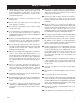
Specifications Heating Specifications Heat Output1 50,000 to 75,000 BTU/hr. Heating Capacity Fuel Burn Rate 2 3 800 - 2,000 sq. ft. 2.0 - 6.0 lbs./hr. Burn Time (lowest setting) 125 hours continuous Hopper Capacity 250 lbs 1 BTU output will vary depending on the quality and type of fuel. Use PFI listed fuels for the best results. Heating capacity will vary depending on floor plan layout of your home, degree of insulation, and the outside temperature.
Fuel Considerations SHELLED CORN (Dry, preferably corn with 11% or less moisture content) • Optimum moisture content of corn should be 11% or less. Wet corn will rapidly deteriorate furnace components, reduce efficiency and void all warranties. Purchase a moisture tester if in doubt. • Corn must be clean and free from debris. Never burn corn right from the field. Damage caused by dirty corn is not covered by the product warranty. Ask for clean filtered bagged corn only.
Installation INSTALLATION OPTIONS Ì Read this entire manual before you install and use your Multi-Fuel Furnace. Failure to follow instructions may result in property damage, bodily injury, or even death! (See specific installation details for clearances and other installation requirements) As a Primary Furnace—the unit functions independently of any other system. The “Room Air” blowers will come on when the plenum and Exhaust temperatures reach a preset point on the furnace’s circuit board (PCB).
Installation CLEARANCES NOTE: Distance on the left-hand side of your Multi-Fuel Furnace is set at 24 inches for suitable access to the control panel and for fuel loading. This distance may be less, but not less than 7 inches.
Installation VENTING REQUIREMENTS Ì Install vent at clearances specified by the vent manufacturer. Ì Do not connect the pellet vent to a vent serving any other appliance or furnace. Ì Do not install a flue damper in the exhaust venting system of this unit. The following installation guidelines must be followed to ensure conformity with both the safety listing of this furnace and to local building codes.
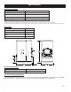
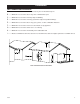
Installation VENT TERMINATION CLEARANCES: A ----- Minimum 4-foot clearance below or beside any door or window that opens. B ----- Minimum 1-foot clearance above any door or window that opens. C ----- Minimum 3-foot clearance from any adjacent building. D ----- Minimum 7-foot clearance from any grade when adjacent to public walkways. E ----- Minimum 2-foot clearance above any grass, plants, or other combustible materials. F ----- Minimum 3-foot clearance from a forced air intake of any appliance.
Installation THROUGH THE WALL INSTALLATION (RECOMMENDED INSTALLATION) To vent the unit through the wall, connect the pipe adapter to the exhaust motor adapter. If the exhaust adapter is at least 18-inches above ground level, a straight section of pellet vent pipe can be used through the wall. Your furnace dealer should be able to provide you with a kit that will handle most of this installation, which will include a wall thimble that will allow the proper clearance through a combustible wall.
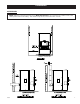
Installation PRIMARY FURNACE SECONDARY (ADD-ON) FURNACE When installed as a seondary furnace, a Duct Damper must be installed between the air discharge of the Pellet furnace and the primary (Gas, Electric, etc.). Damper must be a mechanical (spring return) style damper with a simple closure switch to determine if damper is opened or closed. The damper will connect to the multi fuel furnace’s PCB (Printed Circuit Board). See wiring diagram in this manual.
Operation Ì Do not operate your furnace with the viewing door open. The auger will not feed fuel under these circumstances and a safety concern may arise from sparks or fumes entering the room. Ì A working smoke detector must be installed in the same room as this product. Ì Hopper Lid must be closed during operation. The auger will not feed fuel if the lid is open.
Operation CONTROL PANEL Turning the furnace OFF/ON, as well as adjustments for the fuel feed rate and room fan speed are performed by pressing the appropriate button(s) on the control panel which is located on the lower left-hand side of your American Harvest furnace. This unit can be changed between an automatic operation or a manual operation. The controller comes default in the automatic mode. Pressing the “ON” button on the control panel will begin the start-up sequence for the furnace.
Operation UNIT PREPARATION After carefully unpacking and reading the instructions for installing your furnace, you will need to perform the following steps: 1.) Attach the included spring handle to the door handle by screwing it on in a respective location. 2.) Attach the electrical cord to the back of the furnace first; then plug it into a 110-volt outlet (an outlet surge protector is highly recommended).
Operation DAILY OPERATION Ì The hopper and furnace top will be hot during operation; therefore, you should always use some type of hand protection when refueling your furnace. Ì Never place your hand near the auger while the furnace is in operation. In the event of a power outage, the furnace WILL NOT function. It is very important that unit be vented properly, as the natural draft is needed to clear the smoke from the furnace during a power outage.
Maintenance INTERIOR CHAMBERS Remove the two(2) cleanout plates on each side of the damper control. Using the cleaning tools provided, clean all ash and fuel matter from the burn chamber. This may need to be done daily depending on fuel consumption. Periodically remove and clean the burnpot and the area inside the burnpot housing. In particular it is advisable to clean out the holes in the burnpot to remove any build up that may prevent air from moving through the burn pot freely.
6100 Parts Diagram USSC 17
6100 Parts List Item Part No. Title Qty.
6110 Parts Diagram USSC 19
6110 Parts List 20 USSC
Wiring Diagram USSC 21
Trouble Shooting Ì Disconnect the power cord before performing any maintenance! NOTE: Turning the ON/OFF Switch to ”OFF” does not disconnect all power to the electrical components of the furnace. Ì Never try to repair or replace any part of the furnace unless instructions for doing so are given in this manual. All other work should be done by a trained technician.
Error Codes Below is a chart describing the Error Codes that might be displayed if an error occurs with your furnace. Error Code Error Descrption Possible Causes Err1 The high limit temperature sensor has tripped. • • • • Inadequate ventilation. Room fan failure. Exhaust Blockage. Electrical Open in the over temperature switch or wiring. Err2 Furnace ran out of fuel during normal operation. • • • • Hopper Empty. Auger output failure or jam.
HOW TO ORDER REPAIR PARTS THIS MANUAL WILL HELP YOU OBTAIN EFFICIENT, DEPENDABLE SERVICE FROM YOUR KING OR ASHLEY, AND ENABLE YOU TO ORDER REPAIR PARTS CORRECTLY. KEEP THIS MANUAL IN A SAFE PLACE FOR FUTURE REFERENCE. WHEN WRITING, ALWAYS GIVE THE FULL MODEL NUMBER WHICH IS ON THE NAMEPLATE ATTACHED TO THE HEATER. WHEN ORDERING REPAIR PARTS, ALWAYS GIVE THE FOLLOWING INFORMATION AS SHOWN IN THIS LIST: 1. THE PART NUMBER 2. THE PART DESCRIPTION 3. THE MODEL NUMBER: 6100 4.