
Co. Furnace User Manual
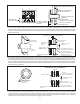


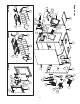

1. Use a minimum 3-1/2" thick brick masonry wall framed into the combustible wall. A reclay liner (ASTM C315 or equivalent) having
a 5/8" minimum wall thickness must be used and it must be at least 12" away from any material that could catch re. The inside
diameter of the reclay liner shall be sized for the proper snug t of a 6" diameter chimney connector pipe. The reclay liner shall
run from the outer surface of the brick wall to, but not beyond, the inner surface of the chimney ue and shall be rmly cemented
in place. See Part A.
MINIMUM 12 IN.
TO COMBUSTIBLES
FIGURE 12, PART A
CHIMNEY FLUE
MINIMUM CHIMNEY CLEARANCE TO
BRICK AND COMBUSTIBLES IS 2 IN.
MINIMUM CLEARANCES 12 IN.
OF BRICK ALL AROUND
CHIMNEY CONNECTOR
TO HEATER
FIRE CLAY LINER
(5/8" MIN. WALL THICKNESS)
MIN. 3-1/2" THICK BRICK
MASONRY WALL
MASONRY CHIMNEY
CONSTRUCTED TO
NFPA 211
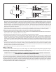
FIGURE 12, PART B
AIR SPACE
9 IN. MINIMUM
FACTORY-BUILT
CHIMNEY LENGTH
MINIMUM CHIMNEY CLEARANCES FROM MASONRY TO
SHEET STEEL SUPPORTS AND COMBUSTIBLES 2 IN.
CHIMNEY LENGTH
FLUSH WITH INSIDE
OF FLUE
NONSOLUBLE
REFACTORY
CEMENT
MASONRY CHIMNEY CONSTRUCTED
TO NFPA 211
CHIMNEY CONNECTOR
TO HEATER
MINIMUM CLEARANCE
9 IN. ALL AROUND
SHEET STEEL SUPPORTS
(24 GAUGE MIN. THICKNESS)
CHIMNEY FLUE
SOLID INSULATED, LISTED
FACTORY-BUILT CHIMNEY LENGTH
USE CHIMNEY MFRS. PARTS TO
ATTACH CONNECTOR SECURELY
AIR SPACE
2. Use a solid insulated listed factory-built chimney length having an inside diameter of 6" and having 1" or more of solid insulation.
There must be at least a 9" air space between the outer wall of the chimney length and any combustible materials. The inner end
of the chimney length shall be ush with the inside of the masonry chimney ue and shall be sealed to the ue and to the brick ma-
sonry penetration with nonwater-soluble refractory cement. Sheet steel supports which are at least 24 gauge (0.024") in thickness
shall be securely fastened to wall surfaces on all sides. Fasteners between supports and the chimney length shall not penetrate
the chimney liner. See Part B.
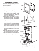
TWO VENTILATED AIR
CHANNELS EACH 1 INCH.
CONSTRUCTED OF
SHEET STEEL.
FIGURE 12, PART C
MASONRY CHIMNEY CONSTRUCTED
TO NFPA 211
SHEET STEEL SUPPORTS
(24 GAUGE MIN. THICKNESS)
MINIMUM CHIMNEY CLEARANCES FROM MASONRY TO
SHEET STEEL SUPPORTS AND COMBUSTIBLES 2 IN.
MINIMUM 6 IN. GLASS
FIBER INSULATION ALL AROUND
24 GAUGE
VENTILATED THIMBLE WITH
TWO 1 INCH AIR CHANNELS
CHIMNEY THIMBLE
CHIMNEY FLUE
CHIMNEY CONNECTOR
TO HEATER
3. Use a 10" diameter ventilated thimble made of at least 24 gauge (0.024") steel having two 1" air channels. The ventilated thimble
must be separated from combustible materials by a minimum of 6" glass ber insulation. The opening in the combustible wall shall
be covered and the thimble supported with sheet steel supports which are at least 24 gauge (0.024") in thickness. The sheet steel
supports shall be securely fastened to wall surfaces on all sides and shall be sized to t and hold the chimney section. Fasteners
used to secure chimney sections shall not penetrate chimney ue liner. See Part C.