
Co. Furnace User Manual


1. The crimped end of the chimney connector ts inside
the furnace ue collar. Install additional chimney con-
nectors and elbow with the CRIMPED END TOWARD
THE FURNACE. This will allow any condensation
in the ue to run back into the furnace. Use 6" dia.
steel pipe and elbows for connection to chimney.
Never use less than 24 gauge and although blued
steel is satisfactory, high temp painted black is much
more desirable. (See Figure 8)
2. Slope any horizontal pipe upward toward the chimney
at least 1/4 inch for each foot of horizontal run.
3. You must have at least 18 inches of clearance be-
tween any horizontal piping and the ceiling.(See Fig.
5)
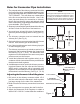
4. The chimney connector must not extend into the
chimney ue. (See Fig. 9)
5. Seal each chimney connector pipe joint with furnace
cement. Also seal the pipe at the chimney.
6. Use 3 sheet metal screws at each chimney pipe joint
to make the piping rigid.
7. The chimney connector may include a section for a
barometric draft regulator between the furnace and
the chimney (Fig. 6, 7, & 10). The barometric draft
regulator must be installed in the same room (same
pressure zone) as the furnace.
8. Install the barometric draft regulator strictly in ac-
cordance with the instructions that are provided with
the barometric draft regulator.
9. A solid damper must be used in the chimney connect-
ing pipes between the ue collar and the chimney.
When used in conjunction with a barometric draft
regulator, the solid damper must be placed between
the barometric and the chimney. (See Fig. 6, 7, & 10)
Adjusting the Barometric Draft Regulator
1. Drill a hole in the chimney connector within 18" of
the ue collar below the barometric draft regulator
just large enough for the tube of the manometer.
2. Build a re after all chimney connections have been
made.
3. Use a manometer to measure the draft in the ue.
4. Adjust the Barometric Draft Regulator to obtain a
draft of 0.05 - 0.06" W.C. under stable re conditions.
RIGHT WRONG WRONG
6" SOLID DAMPER
6" BAROMETRIC
DRAFT REGULATOR
NON COMBUSTIBLE
INSTALLATION PER
NFPA 211
MEASURE FLUE DRAFT HERE
Rules for Connector Pipe Installation
NOTE:
A ue pipe shall not pass through an attic, roof
space, closet or similar concealed space, a oor
or ceiling of combustible construction. Where
passage through a wall or partition is desired,
installation must conform with UL standards.