Models 3500, 3500PB & 3700, 3700PB OWNER'S MANUAL CAST IRON ROOM HEATER SAFETY NOTICE: If this solid fuel room heater is not properly installed, a house fire may result. For your safety and to reduce the risk of fire, follow the installation directions. Contact local building, fire officials, or the authority having jurisdiction about restrictions and installation inspection requirements in your area. Kindly save these instructions for future reference.
Introduction Congratulations on purchasing a U.S. Stove Product. When cared for properly, the high quality, finely crafted cast iron stove will offer many years of reliable performance. This instruction manual has been developed to ensure optimum performance from your Forester stove. It's very important that you thoroughly read and understand all instructions before using your new stove.
Stove Safety IT IS YOUR OR THE INSTALLER’S RESPONSIBILITY TO READ ALL SAFETY PRECAUTIONS AND FOLLOW THE PRESCRIBED DIRECTIONS. When properly maintained and operated your stove should give you many years of service. However there are important safety aspects of these products that you need to be aware of when operating a wood stove. 1. ONLY USE SOLID WOOD FUEL.
Check Building Codes When installing, operating and maintaining your stove, follow the guidelines presented in these instructions, and make them available to anyone using or servicing the stove. Your city, town, county or province may require a building permit to install a solid fuel burning appliance. In the U.S.
Installation Unpacking and preparing your stove for installation. 1. Remove your stove from the outer packaging and place on floor. Please inspect stove and check that it is not damaged in any way. Never attempt to use a stove that has been damaged. 2. If you are installing the stove yourself, proceed as follows. However, if you are unsure about any aspect of stove installation, please contact your dealer and he will discuss installation with you or put you in touch with an experienced stove installer. 3.
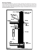
Installation Clearances It is extremely important that you respect required installation distances and that you respect local installation regulations. This is for your safety! The manufacturer is not responsible for the product, if it is not installed following these recommendations. These clearances may only be reduced by means approved by the regulatory authority.
Installation Clearances Only materials and items approved for solid fuel stoves should be used for your stove. Under no circumstances should you use aluminum or galvanized steel pipes for your stove flue. Always fit pipes with the narrow side down, this allow any creosote to run down the inside of the pipe and not to come out and cause an unsightly mess and possible fire hazard. All joints in the flue system should be sealed with fire cement and/or an appropriate fire resistant rope or gasket.
This prevents any amount of condensed or liquid creosote from running down the outside of the pipe or the stove top. All joints, including the flue collar connection must be secured with three sheet metal screws to ensure that the sections do not separate. For the best performance the chimney connector should be as short and direct as possible, with no more than two 90° elbows. The maximum horizontal run is 36” and a recommended total length of stovepipe should not exceed 10 feet.
Factory Built Chimney When a metal prefabricated chimney is used, the manufacturer’s installation instructions must be followed. You must also purchase (from the same manufacturer) and install the ceiling support package or wall pass-through and “T” section package, firestops (where needed), insulation shield, roof flashing, chimney cap, etc. Maintain proper clearance to the structure as recommended by the manufacturer.
Masonry Chimney Ensure that a masonry chimney meets the minimum standards of the National Fire Protection Association (NFPA) by having it inspected by a professional. Make sure there are no cracks, loose mortar or other signs of deterioration and blockage. Have the chimney cleaned before the stove is installed and operated. When connecting the stove through a combustible wall to a masonry chimney, special methods are needed.
Combustible Wall Chimney Connector Pass-Throughs Method A. 12” (304.8 mm) Clearance to Combustible Wall Member: Using a minimum thickness 3.5” (89 mm) brick and a 5/8” (15.9 mm) minimum wall thickness clay liner, construct a wall pass-through. The clay liner must conform to ASTM C315 (Standard Specification for Clay Fire Linings) or its equivalent. Keep a minimum of 12” (304.8 mm) of brick masonry between the clay liner and wall combustibles.
Operating Your Stove Do not use a grate, andiron or other fuel support method. Build fire directly on the hearth. Only open door to fuel/refuel the stove. Excess air can cause the stove to over fire. Do not over fire, if chimney or stove is glowing red you are over firing. Do not build the fire too close to the glass. Do not abuse the glass doors. Do not strike or slam shut the door. DO NOT USE CHEMICALS OR FLUIDS TO START THE FIRE.
Refueling Before refueling your stove, turn the air supply to high for a few moments until there is a good fire in the stove. This will ensure there is no build-up of harmful gases in the stove when the door is opened and will also get the new fuel burning quickly and not allow it to kill the fire. To reload the stove, open the door and feed the fuel in slowly using tongs or a small shovel. Do not overfill the stove. It is always better to put in small loads often rather than big fills less frequently.
When you return to your stove, fully open both air controls until you have a good fire and then set to normal operating levels. Do not add fuel until the fire bed is hot and red. Then add a little for the first time and allow that to ignite before adding more. During overnight burning, the stove glass will blacken, but when a hot fire is established again this should burn off.
Replacement of Glass 1. Remove the door from the stove and place on a flat surface. 2. Carefully remove all of the glass clips from the inside of the door. 3. Gently remove the glass panel and gasket. 4. Using a wire brush, remove all remaining debris from the glass area. 5. Apply a small bead of gasket/stove cement and the new gasket. Do not overlap the ends of the gasket rope. 6. Center the new glass panel over the gasket and reinstall the glass clips. 7.
Smoke in Room If the stove is properly installed it should not emit any smoke into your room. Should this happen, Check that your room is not air tight. This can easily be checked by opening a door or window. If the smoking stops you need to provide an additional air supply into the room. If this is not the problem, check if your chimney is blocked or obstructed and that you are not getting a down draft caused by the location of the open end of the flue pipe or chimney.
Warranty Policy & Procedures U.S. Stove offers the original retail purchaser of the Solid Fuel burning products a limited 5-year warranty. The following outlines the U. S. Stove's Warranty programs. U. S. Stove Limited Warranty This warranty applies to the original retail purchaser only. U. S. Stove warrants that this stove will be free of defects in material and workmanship for a period of five years from the date of purchase. U. S.
3500, 3500PB Parts Diagram & List 1 11 2 34 5 6 7 17 18 19 20 21 8 9 10 25 24 12 13 14 15 22 23 38 37 36 39 26 16 27 41 33 32 34 28 29 30 35 31 40 KEY PART # DESCRIPTION 1 2 3 4 5 6 7 8 9 10 11 12 13 14 15 16 17 18 19 20 21 40517 40518 40519 891689 40520 40521 40522 40523 40524 40525 891690 40526 891691 891692 40527 891693 891694 40528 40529 40530 40531 Hob (HF517U-1) Top Frame Casting (HF517U-2) Secondary Air Deflector Plate (HF517U-3) Small Cover Plate (HF517U-4) Top Baffle (HF517U-5) Fro
3700, 3700PB Parts Diagram & List 1 22 55 33 66 77 88 41 46 40 45 10 10 44 14 13 38 43 39 44 11 12 12 13 orse 99 lame 25 28 43 48 37 42 36 35 40 27 32 26 33 38 34 39 22 25 orse lam e 42 47 141515 16 16 17 18 31 3632 37 20 21 30 35 29 34 28 33 KEY PART # DESCRIPTION 1 2 3 4 5 6 7 8 9 10 11 12 13 14 15 16 17 18 19 20 21 22 40539 40540 891716 891717 891718 40541 40542 40543 891719 40544 891720 891721 40546 40547 40548 891722 891723 40549 40550 40551 891724 891725 Hob (HF717U-1) T
How to order repair parts THIS MANUAL WILL HELP YOU OBTAIN EFFICIENT, DEPENDABLE SERVICE FROM YOUR FURNACE, AND ENABLE YOU TO ORDER REPAIR PARTS CORRECTLY. KEEP THIS MANUAL IN A SAFE PLACE FOR FUTURE REFERENCE. WHEN WRITING, ALWAYS GIVE THE FULL MODEL NUMBER WHICH IS ON THE NAMEPLATE ATTACHED TO THE HEATER. WHEN ORDERING REPAIR PARTS, ALWAYS GIVE THE FOLLOWING INFORMATION AS SHOWN IN THIS LIST: 1. THE PART NUMBER 2. THE PART DESCRIPTION 3.