UNITED STATES STOVE COMPANY “Keeping North America Warm Since 1869” MULTI-FUEL FURNACE MODEL SP8500 Approved for US and Canadian use. Safety tested and listed to UL 391-2010, ASTM E1509-04, and CSA-B366.1-11 Certified for installation in a residential or mobile home as a stand-alone or add-on furnace (ductwork connection only). TESTED & LISTED BY PORTLAND, OREGON, USA Report #: 215-S-22b-2 Owner’s Manual Please read this entire manual before installation and use of this appliance.
Table of Contents TABLE OF CONTENTS .............................................................................................. 2 SAFETY PRECAUTIONS ........................................................................................... 3 SPECIFICATIONS....................................................................................................... 4 Heating Specifications ..................................................................................... 4 Dimensions ........................
Safety Precautions IMPORTANT: Read this entire manual before installing and operating this product. Failure to do so may result in property damage, bodily injury, or even death. Proper installation of this furnace is crucial for safe and efficient operation. Contact your local building officials to obtain a permit and information on any additional installation restrictions or inspection requirements in your area. DO NOT throw this manual away.
Specifications Heating Specifications Input BTU/Hr1 50,000 to 105,000 BTU/hr. Heating Capacity Fuel Burn Rate 2 3 1,200 - 2,800 sq. ft. 5.0 - 13.0 lbs./hr. Burn Time (lowest setting) 70 hours continuous Hopper Capacity 160 lbs BTU output will vary depending on the quality and type of fuel. Use PFI listed fuels for the best results. Heating capacity will vary depending on floor plan layout of your home, degree of insulation, and the outside temperature.
Fuel Considerations SHELLED CORN (Dry, preferably corn with 11% or less moisture content) • Optimum moisture content of corn should be 11% or less. Wet corn will rapidly deteriorate furnace components, reduce efficiency and void all warranties. Purchase a moisture tester if in doubt. • Corn must be clean and free from debris. Never burn corn right from the field. Damage caused by dirty corn is not covered by the product warranty. Ask for clean filtered, bagged corn only.
Installation INSTALLATION OPTIONS Read this entire manual before you install and use your Multi-Fuel Furnace. Failure to follow instructions may result in property damage, bodily injury, or even death! (See specific installation details for clearances and other installation requirements) Certified for installation in a Residentail Type home in the USA and Canada. Also may be installed into a Manufactured or Mobile Home. As a Primary Furnace—the unit functions independently of any other system.
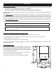
Installation CLEARANCES NOTE: Distance on the left-hand side of your Multi-Fuel Furnace is set at 24 inches for suitable access to the control panel and for fuel loading. This distance may be less, but not less than 7 inches.
Installation VENTING REQUIREMENTS Install vent at clearances specified by the vent manufacturer. Do not connect the pellet vent to a vent serving any other appliance or furnace. Do not install a flue damper in the exhaust venting system of this unit. INSPECT EXHAUST VENTING (joints, seals, etc.) REGULARLY TO ENSURE THAT SMOKE AND FLUE GASES ARE NOT DRAWN INTO AND CIRCULATED BY THE AIR CIRCULATION SYSTEM.
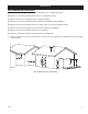
Installation VENT TERMINATION CLEARANCES: A) Minimum 4-foot (1.22m) clearance below or beside any door or window that opens. B) Minimum 1-foot (0.3m) clearance above any door or window that opens. C) Minimum 3-foot (0.91m) clearance from any adjacent building. D) Minimum 7-foot (2.13m) clearance from any grade when adjacent to public walkways. E) Minimum 2-foot (0.61m) clearance above any grass, plants, or other combustible materials. F) Minimum 3-foot (0.
Installation THROUGH THE WALL INSTALLATION (RECOMMENDED INSTALLATION) To vent the unit through the wall, connect the pipe adapter to the exhaust motor adapter. If the exhaust adapter is at least 24-inches above ground level, a straight section of pellet vent pipe can be used through the wall. Your furnace dealer should be able to provide you with an installation kit, which will include a wall thimble that will allow the proper clearance through a combustible wall.
Installation PRIMARY FURNACE This appliance requires the installation of a cold air return duct system. The return air will provide a better distribution of warm air throughout your home, making the unit much more efficient than if installed without a return system. This appliance must be installed by experienced personnel and in accordance with the instructions of the manufacturer and in a manner acceptable to the authority having jurisdiction.
Component Location CLEANOUT TOOL ASH CLEANOUTS STAINLESS STEEL BAFFLE EXHAUST CLEANOUT (located behind the ash pan) 12 USSC
Operation CONTROL PANEL Turning the furnace OFF/ON, as well as adjustments for the fuel feed rate and room fan speed are performed by pressing the appropriate button(s) on the control panel which is located on the lower left-hand side of your Breckwell furnace. This unit can operate in either automatic or manual mode. Automatic mode has pre-set default settings. Pressing the “ON” button on the control panel will begin the start-up sequence for the furnace.
LIGHTING INSTRUCTIONS CAUTION: DO NOT USE CHEMICALS OR FLUIDS TO START THE FIRE HOT WHILE IN OPERATION. KEEP CHILDREN, CLOTHING AND FURNITURE AWAY. CONTACT MAY CAUSE SKIN BURNS. Before lighting your heater for the first time, make sure that all items are out of the hopper, ash pan and firebox area. Press the “On” button and allow your heater to run for at least 4 minutes, to check for proper operation. Once your heater is started, you will notice that the draft fan starts immediately.
Operation DAILY OPERATION The hopper and furnace top will be hot during operation; therefore, you should always use some type of hand protection when refueling your furnace. Never place your hand near the auger while the furnace is in operation. In the event of a power outage, the furnace WILL NOT function. It is very important that unit be vented properly, as the natural draft is needed to clear the smoke from the furnace during a power outage.
Maintenance INTERIOR CHAMBERS Open the Ash Cleanouts and scrap all ash into the ash pan. Open the damper and allow the ashes to fall into the ash pan. The damper may need to be slid in and out several times to clear any ash build-up. This may need to be done daily depending on fuel consumption. Be sure the ash cleanouts located on either side of the damper are completely closed before operating. Periodically remove and clean the burnpot and the area inside the burnpot housing.
Parts Diagram 64 6 62 7 32 13 50 59 3 10 19 9 63 8 22 31 30 29 18 23 11 4 54 58 56 51 24 39 57 61 12 65 52 28 25 49 21 26 29 28 28 29 16 53 26 46 41 50 1 47 35 44 45 48 37 16 17 20 34 33 38 40 60 43 2 27 36 42 5 17 USSC
Parts List 1 23786 Door Latch (C000022) 1 34 891331 Spring Handle-Brushed Nickel 2 24179 Feed Door Handle 1 35 891364 Hearth Plate 1 3 25427 Retainer, Agitator Motor 1 36 891374 Access Panel, Plenum 1 4 40501 Agitator, Cast 1 37 891423 Pin, Door Hinge 2 5 69679 Assembly, Feed Door (Blank) 1 38 891445 Ash Pan Assembly 1 6 80461 Power Supply Cord 1 39 891455 Weldment, Burnpot 1 7 80462 Receptacle, 3 Prong 1 40 891461 Cover, Exhaust Cleanout 1 8 80488 Dr
Wiring Diagram Amendment USSC 19
Trouble Shooting Disconnect the power cord before performing any maintenance! NOTE: Turning the ON/OFF Switch to ”OFF” does not disconnect all power to the electrical components of the furnace. Never try to repair or replace any part of the furnace unless instructions for doing so are given in this manual. All other work should be done by a trained technician.
Error Codes Below is a chart describing the Error Codes that might be displayed if an error occurs with your furnace. Error Code Error Description Possible Causes Err1 The high limit temperature sensor has tripped. • • • • Inadequate ventilation. Room fan failure. Exhaust Blockage. Electrical Open in the over temperature switch or wiring. Err2 Furnace ran out of fuel during normal operation. • • • • Hopper Empty. Auger output failure or jam.
HOW TO ORDER REPAIR PARTS THIS MANUAL WILL HELP YOU OBTAIN EFFICIENT, DEPENDABLE SERVICE FROM YOUR BRECKWELL UNIT, AND ENABLE YOU TO ORDER REPAIR PARTS CORRECTLY. KEEP THIS MANUAL IN A SAFE PLACE FOR FUTURE REFERENCE. WHEN WRITING, ALWAYS GIVE THE FULL MODEL NUMBER WHICH IS ON THE NAMEPLATE ATTACHED TO THE HEATER. WHEN ORDERING REPAIR PARTS, ALWAYS GIVE THE FOLLOWING INFORMATION AS SHOWN IN THIS LIST: 1. THE PART NUMBER 2. THE PART DESCRIPTION 3. THE MODEL NUMBER: SP8500 4.
CUT HERE WARRANTY INFORMATION CARD Name__________________________________________ Telephone #: (_____)_____________ City____________________________________________ State_______ Zip_________________ Email Address __________________________________________________________________ Model # of Unit________________________________ Serial #___________________________ Fuel Type: Wood Coal Pellet Gas Other _________________________ Place of Purchase (Retailer)___________________________________________
CUT HERE Fold Here Fold Here United States Stove Company P.O.