UNITED STATES STOVE COMPANY 227 INDUSTRIAL PARK ROAD • P.O. BOX 151 • SOUTH PITTSBURG, TN. 37380 • (423)-837-2100 Natural Gas Model C9947N Propane (LPG) Gas Model C9947L Owner's Operation and Installation Manual This appliance may be installed in an aftermarket* manufactured (mobile) home, where not prohibited by state or local codes. *Aftermarket: Completion of sale, not for purpose of resale, from the manufacturer This appliance is only for use with the type gas indicated on the rating plate.
TABLE OF CONTENTS SECTION PAGE IMPORTANT SAFETY INFORMATION.......................................................3-4 PRODUCT FEATURES..................................................................................4 9947 SPECIFICATIONS.................................................................................5 CONTENTS....................................................................................................5 ITEMS REQUIRED FOR INSTALLATION.................................................
IMPORTANT SAFETY INFORMATION INSTALLER: Please leave these instructions with the owner. OWNER: Please retain these instructions for future reference. IMPORTANT: Read these instructions carefully before installing or trying to operate this heater. WARNING: Any change to this heater or its controls can be dangerous. Improper installation or use of the heater can cause serious injury or death from fire, burns, explosion or carbon monoxide poisoning. 1.
IMPORTANT SAFETY INFORMATION CONTINUED 13. Keep appliance area clear and free from combustible materials, gasoline and other flammable vapors and liquids. 15. Any safety screen or guard removed for servicing, must be replaced prior to heater operation. 16. This vent-free gas heater is intended to be smokeless. If logs appear to smoke, turn off the heater and call a qualified service person. Initial burn off may cause slight smoke and odor during the first four hours of operation. 17.
9947 SPECIFICATIONS Natural Gas Manifold Pressure Setting: Gas Inlet Pressure: Maximum Minimum Model Number 9947N 9947L Type Manual Manual 4" w.c. 10-1/2" w.c. 5" w.c. Propane/LPG Manifold Pressure Setting: Gas Inlet Pressure: Maximum Minimum Gas Rate Max BTU/Hr Min BTU/Hr 39,900 27,000 39,900 27,000 10" w.c. 13" w.c. 11" w.c. Number of Burners 1 1 Controls - Main control has 4 positions: 1. OFF - All gas to the gas logs is shut off at the control 2.
ITEMS REQUIRED FOR INSTALLATION ITEMS REQUIRED FOR INSTALLATION Ensure that the following items are available before proceeding with installation: • External regulator (for propane/LPG only) • Piping which complies with local codes • Pipe sealant approved for use with propane / LPG (resistant to sulfur compounds) • Manual cutoff valve • Sediment trap • Pipe wrench CODES Adhere to all local codes or in their absence, the latest edition of THE NATIONAL FUEL GAS CODE ANSIZ223.
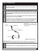
INSTALLATION The following formula can be used to determine the maximum heater rating per the definition of unconfined space: BTU/HR = (L1+L2) Ft x (W) Ft x (H) Ft x 1000 50 Consider two connecting rooms with an open area between, with the following dimensions:( See Fig. 2, Example) L1=15-1/2 Ft., L2=12 Ft., W=12 ft., H=8Ft 50 =52800 BTU/HR If there were a door between the two rooms the calculation would be based only on the room with the heater.
MANTEL CLEARANCES If placing a custom mantel above the heater, you must meet minimum clearances between mantel shelf and the top of the heater. If your installation does not meet the below minimum clearances, you must: • Raise the mantel to an acceptable height, OR • Remove the mantel. MINIMUM MANTEL CLEARANCES Figure 4.
CAUTION NOTICE GAS CONNECTION A qualified gas appliance installer must connect the fireplace to the gas supply. Consult all local codes. Use new black iron or steel pipe only. Internally tinned copper tubing can be used in some areas when permitted by local codes. Only use pipe of 1/2" or greater diameter to allow full gas volume to heater. Excessive pressure loss will occur if the pipe is too small.
GAS CONNECTION The gas inlet connection is 3/8" NPT, made at the rear of the unit in the bottom left-hand corner. Test all gas joints from the gas meter to the heater for leaks using soap and water solution after completing connection. DO NOT USE AN OPEN FLAME. Gas Inlet Connection (3/8" NPT) FIGURE 6.
REMOVING FRONT SCREEN REMOVING FRONT SCREEN: 1) Remove screw from the top of the screen (Fig. 8A). 2) Tilt the top of the screen toward you slightly and lift the screen up out of the screen retainer (Fig. 8B). NOTE: To reinstall the front screen, reverse steps 1 & 2. FIG. 8A FIG. 8B LOG ASSEMBLY LOG POSITIONING Do not handle these logs with your bare hands! Always wear gloves to prevent skin irritation from ceramic fibers.
OPERATING INSTRUCTIONS Avoid any drafts that alter the burner flame patterns. Do not allow fans to blow directly into the heater. Do not place a blower inside burn area of firebox. Ceiling fans may create drafts that alter burner flame patterns. Sooting and improper burning will occur. This vent-free gas heater is intended to be smokeless. If logs appear to smoke, turn off the heater and call a qualified service person.
OPERATING INSTRUCTIONS LIGHTING INSTRUCTIONS 1. 2. 2. 3. 5. STOP! Read the safety information on the previous page. Set the thermostat to lowest setting. Turn off all electrical power and open the access door. Push in gas control (B) slightly and turn clock wise to "OFF". Push "ON / OFF" switch to "OFF" position. B D A C NOTE: Knob cannot be turned from "PILOT" to "OFF" unless knob is pushed in slightly. Do not force. 6. 7. 8. Wait five (5) minutes to clear out any gas.
WARNING OPERATING INSTRUCTIONS Wait 30 seconds before readjusting the heater when the control has been turned down to a lower setting. MATCH LIGHTING INSTRUCTIONS If the pilot will not light using the piezo ignitor, you can light the pilot with a match. First, locate the pilot. The pilot is located between the two burner tubes on the right end (facing the unit), inside the firebox. To light pilot with a match, move the gas control (knob B, pg. 12) to the pilot position and hold down.
CLEANING / SERVICING Periodic Cleaning • Do not use cleaning fluid to clean logs or any part of heater. • Logs - Brush with soft bristle brush or vacuum with brush attachment. • Vacuum loose particles and dust from the front and rear burner, control, and piezo. • Inspect burner's and air intake hole. Remove lint or particles with vacuum. • External case should be dusted and wiped with a wet soapy cloth. Annual Cleaning/Inspection • Inspect and clean burner air intake holes.
HEATER ASSEMBLY 16
PARTS LIST KEY 1 2 3 4 5 6 7 8 9 10 11 12 13 14 15 16 17 18 19 20 21 22 23 24 25 N/S 26 27 28 29 N/S 30 31 32 33 • 34 N/S N/S N/S N/S N/S PART NO.
BURNER AND LOG ASSEMBLY 20 19 18 2 3 4 5 6 1 13 17 14 16 15 10 12 11 8 9 7 18
PARTS LIST KEY PART NO. 1 24777 2 89920 3 89921 • 89922 N/S 83172 4 89842 5 89841 6 81201 7 24788 8 81198 • 81202 9 83464 10 89918 • 89923 11 C42373 12 80376 13 89761 14 80423 15 81199 16 81200 17 24888 18 89940 19 89939 20 89941 N/S = NOT SHOWN DESCRIPTION BURNER PLATE BURNER "O.P. AMERICA" NAT. PILOT "O.P. AMERICA" L.P. PILOT #10A x 1/2 SCREW COMPRESSION SLEEVE COMPRESSION NUT PILOT TUBE CONTROL BRACKET CONTROL VALVE (NATURAL) CONTROL VALVE (L.P.
WARNING TROUBLE SHOOTING Turn off and let cool before servicing. Only a qualified service person should service and repair heater. NOTE: All troubleshooting items are listed in order of operation. OBSERVED PROBLEM When ignitor button is pressed, there is no spark at ODS/Pilot. Appliance produces unwanted odors. POSSIBLE CAUSE REMEDY • Ignitor electrode positioned wrong • Replace ignitor. • Ignitor electrode is broken • Replace ignitor. • Ignitor electrode not connected to ignitor cable.
TROUBLE SHOOTING OBSERVED PROBLEM ODS/Pilot lights, but flame goes out When control knob is released. (continued from page 20) One or both burner do not light after ODS/pilot is lit. POSSIBLE CAUSE REMEDY • Thermocouple connection loose at control valve. • Pilot flame not touching thermocouple, which allows thermocouple to cool, causing pilot flame to go out. This problem could be caused by either low gas pressure, or a dirty or partially clogged ODS/pilot. • Thermocouple damaged.
OPTIONAL EQUIPMENT SKY TEC H INDICATOR SKY TEC ON H OFF NO R E M O T E R EM O TE OFF SKYTECH 1001 MODEL: RCK60 REMOTE CONTROL KIT MODEL: WSK60 WALL SWITCH KIT 10 21 32 c 50 60 70 80 90 10 21 32 c 50 60 70 80 90 MODEL: WTK60 WALL THERMOSTAT KIT 22
WIRING DIAGRAM FOR BLOWER ASSEMBLY 1/4"FEMALE INS. 1/4" MALE INS. WHITE (NEUTRAL) BLACK (HOT) 1/4"FEMALE INS. GREEN (GROUND) 1/4" MALE INS. BLOWER BLACK 1/4" FEMALE INS. BLACK 1/4" MALE INS. 80426 (12") 80425 (28") 1/4"FEMALE INS. 1/4"FEMALE INS.
WIRING GUIDE FOR 9947 The following Wiring Guide is to help assist in the wiring of any combination of the Optional Kit listed below: RCK60 - REMOTE CONTROL KIT WSK60 - WALL SWITCH KIT WTK60 - WALL THERMOSTAT KIT IMPORTANT: Before ordering or installing any to the available kits, remember the following... 1) Not all Optional Kits will work together. Example: The (RCK60) Remote Control Kit, the (WSK60) Wall Switch Kit, and the (WTK60) Wall Thermostat Kit cannot be used at the time.
WIRING WITH THE WSK60 - WALL SWITCH KIT: WALL SWITCH Remember the Rocker Switch must be turned to "OFF" while using the Wall Switch. CONTROL VALVE ROCKER SWITCH PIGGYBACK DISCONNECT WIRING WITH THE WTK60 - WALL THERMOSTAT KIT AND THE RCK60 - REMOTE CONTROL KIT: Note: When combining these Optional kits, only one kit can be used at a time. Example: If you want to control the operation of this unit with the Remote Control then you must turn the Wall Thermostat "OFF".
NOTES 26
LIMITED WARRANTY POLICY This vent-free gas heater is warrantied for a period of one year, logs for one year, and burners for One Year, from date of purchase against defects in material or workmanship. This warranty covers only the cost of defective parts and applies only to the original consumer purchaser. The replacement of defective parts will be without charge.
OWNERS MANUAL HOW TO ORDER REPAIR PARTS OR "OPTIONS" THIS MANUAL WILL HELP YOU TO OBTAIN EFFICIENT, DEPENDABLE SERVICE FROM THE FURNACE, AND ENABLE YOU TO ORDER REPAIR PARTS CORRECTLY. KEEP IN A SAFE PLACE FOR FUTURE REFERENCE. WHEN WRITING, ALWAYS GIVE THE FULL MODEL NUMBER WHICH IS ON THE NAME PLATE ATTACHED TO THE BACK OF THE HEATER. WHEN ORDERING REPAIR PARTS OR OPTIONS, ALWAYS GIVE THE FOLLOWING INFORMATION AS SHOWN IN THIS LIST: 1. The PART NUMBER 2. The PART DESCRIPTION 3.
REMOVING FRONT SCREEN 1) Lift the front screen slightly up (Fig. 2A) and then tilt the bottom of the screen inward and downward (Fig. 2B). 2) Lean the top of the screen toward you slightly (Fig. 2B) and then proceed to carefully bring the screen straight back (Fig. 2C). NOTE: To reinstall the front screen, reverse steps 1 & 2. FIG 2A FIG 2B FIG 2C LOG ASSEMBLY LOG POSITIONING This unit is supplied with a set of four ceramic fiber logs.
OPERATING INSTRUCTIONS Avoid any drafts that alter the burner flame patterns. Do not allow fans to blow directly into the heater. Do not place a blower inside burn area of firebox. Ceiling fans may create drafts that alter burner flame patterns. Sooting and improper burning will occur. This vent-free gas heater is intended to be smokeless. If logs appear to smoke, turn off the heater and call a qualified service person.
OPERATING INSTRUCTIONS LIGHTING INSTRUCTIONS 1. 2. 3. 4. PILOT LOCATION STOP! Read the safety information on the previous page. Turn off all electrical power and open the access door. Turn off the rear burner and set the front burner to low. Push in gas control (knob 1) slightly and turn clockwise to "OFF". TOP VIEW OF BURNER ASSEMBLY KNOB 3 6. Push in the control (knob 1) all the way and rotate counterclockwise to "PILOT".
WARNING OPERATING INSTRUCTIONS Wait 30 seconds before readjusting the heater when the control has been turned down to a lower setting. MATCH LIGHTING INSTRUCTIONS If the pilot will not light using the piezo ignitor, you can light the pilot with a match. First, locate the pilot. The pilot is located between the two burner tubes on the right end (facing the unit), inside the firebox. To light pilot with a match, move the gas control (knob 1, pg. 12) to the pilot position and hold down.
CLEANING / SERVICING Periodic Cleaning • Do not use cleaning fluid to clean logs or any part of heater. • Logs - Brush with soft bristle brush or vacuum with brush attachment. • Vacuum loose particles and dust from the front and rear burner, control, and piezo. • Inspect burner's and air intake hole. Remove lint or particles with vacuum. • External case should be dusted and wiped with a wet soapy cloth. Annual Cleaning/Inspection • Inspect and clean burner air intake holes.
HEATER ASSEMBLY REPLACEMENT PARTS 1 2 3 4 5 13 6 11 7 10 9 8 15 12
PARTS LIST FOR HEATER ASSEMBLY KEY 1 2 3 4 5 6 7 8 PART # 69113 69134 69065 69102 69070 24469 69084 24455 9 10 11 12 13 N/S N/S 24457 89899 83323 24536 89825 89824 83172 DESCRIPTION CABINET TOP WELDMENT FIREBOX BACK WELDMENT FIREBOX TOP WELDMENT INSIDE BACK WELDMENT FIREBOX WELDMENT FIREBOX BOTTOM PEDESTAL WELDMENT PEDESTAL BASE CONTROL DOOR BRASS KNOB 8-32 x 3/8 PH MACHINE SCREW FRONT SCREEN (PAINTED) BRASS TRIM MAGNETIC LATCH #10A x 1/2 HX W SM SCREWS QTY.
BURNER & LOG ASSEMBLY 17 11 1 13 14 12 20 7 9 8 16 10 4 19 15 18 D 6 3 C B 2 A 5 17
PARTS LIST FOR GAS LOG ASSEMBLY KEY 1 2 3 4 5 N/S 6 7 8 9 10 11 12 N/S 13 14 15 16 17 18 a b c d 19 N/S 20 PART # 24610 24611 81189 81190 83251 83244 83343 89831 89834 89838 89839 89840 24612 89872 89873 83437 89841 89842 89829 89836 89830 89836 24613 89826 89826-1 89826-2 89826-3 89826-4 89856 86318 89855 DESCRIPTION BURNER PLATE CONTROL BRACKET CONTROL VALVE (NATURAL) CONTROL VALVE (L.P.
WARNING TROUBLESHOOTING Turn off and let cool before servicing. Only a qualified service person should service and repair heater. NOTE: All troubleshooting items are listed in order of operation. OBSERVED PROBLEM When ignitor button is pressed, there is no spark at ODS/Pilot. Appliance produces unwanted odors. POSSIBLE CAUSE REMEDY Ignitor electrode positioned wrong Replace ignitor. Ignitor electrode is broken Replace ignitor. Ignitor electrode not connected to ignitor cable.
TROUBLESHOOTING, CONTINUED... OBSERVED PROBLEM ODS/Pilot lights, but flame goes out When control knob is released. (continued from page 17) One or both burner do not light after ODS/pilot is lit. POSSIBLE CAUSE REMEDY Thermocouple connection loose at control valve. Pilot flame not touching thermocouple, which allows thermocouple to cool, causing pilot flame to go out. This problem could be caused by either low gas pressure, or a dirty or partially clogged ODS/pilot. Thermocouple damaged.
OPTIONAL F40 BLOWER KIT THIS OPTIONAL F40 BLOWER KIT IS AVAILABLE WHERE YOU PURCHASED THIS HEATER OR YOU CAN ORDER DIRECT FROM THE FACTORY BY CONTACTING THE PARTS DEPARTMENT AT THE NUMBER AND ADDRESS ON THE BACK PAGE OF THIS MANUAL.
NOTES 22
LIMITED WARRANTY POLICY This vent-free gas heater is warrantied for a period of one year, logs for one year, and burners for One Year, from date of purchase against defects in material or workmanship. This warranty covers only the cost of defective parts and applies only to the original consumer purchaser. The replacement of defective parts will be without charge.
OWNERS MANUAL HOW TO ORDER REPAIR PARTS OR "OPTIONS" THIS MANUAL WILL HELP YOU TO OBTAIN EFFICIENT, DEPENDABLE SERVICE FROM THE FURNACE, AND ENABLE YOU TO ORDER REPAIR PARTS CORRECTLY. KEEP IN A SAFE PLACE FOR FUTURE REFERENCE. WHEN WRITING, ALWAYS GIVE THE FULL MODEL NUMBER WHICH IS ON THE NAMEPLATE ATTACHED INSIDE THE FRONT OF THE HEATER. WHEN ORDERING REPAIR PARTS OR OPTIONS, ALWAYS GIVE THE FOLLOWING INFORMATION AS SHOWN IN THIS LIST: 1. The PART NUMBER 2. The PART DESCRIPTION 3.