USSC E U STATES STO TED V I N COMPANY Installation/Operator’s Manual Model: 1602M Wood or Coal Gravity Style (Up-Flow) Supplemental Furnace SAFETY NOTICE: If this furnace is not properly installed, a house fire may result! For your safety, follow these installation instructions. Contact local building or fire officials about restrictions and installation requirements in your area. This furnace must be installed by a qualified technician. Keep these instructions for future reference.
Thank You for your purchase of a U.S. Stove Wood/Coal Burning Gravity Style (Up-Flow) Furnace. Your decision to buy our Clayton Furnace was undoubtedly reached after much careful thought and consideration. We are very proud you chose this furnace and trust you will receive the comfort and economy that others realize when heating with a U.S. Stove product.
CHIMNEY REQUIREMENTS A fireclay lined masonry or Class A 103HT All-Fuel Metal Insulated Chimney must be used in all airtight wood furnace installations. The minimum recommended flue size for the model 1602 is 6 inches, inside diameter. When making new chimney installations, always follow the chimney manufacturer’s instructions. If at all possible, use the factory built, class A 103HT chimney mentioned above. They are safer and perform better than traditional masonry chimneys.
IMPORTANT INFORMATION FOR ALL CONNECTOR PIPES The connector pipe must be constructed and installed so that it maintains clearances, keeps condensation and creosote within the pipe, and is capable of withstanding a 2100°F degree chimney fire. 1. The connector pipe should slant down toward the furnace a minimum of 1/4” to the foot. At no time should the pipe turn downward toward the chimney or run horizontal. 2. There should be no more than two 90 degree elbows. 3.
INSTALLATION #2 Extending the hot air duct from the furnace into the existing plenum will help direct the flow of air from the furnace as well as the flow in the existing furnace. Ducting entering the existing plenum at an angle (approximately 45 degrees) will facilitate air flow from the furnace while diverting air from the existing furnace. INSTALLATION #3 The baffle on this system should be made the full width of the furnace plenum in order to properly direct the air into the distribution ducts.
FURNACE ASSEMBLY INSTRUCTIONS Unpack your Furnace and insure that there is no shipping damage. If damage exist, please contact your dealer immediately. Your Clayton Furnace will require some assembly before operation. All needed hardware and components for the following assemblies are included within the parts boxes inside the furnace and in the ash pan. Read and follow these instructions for proper furnace assembly. DOOR HANDLES Insert door handle into door.
SPIN DAMPER Screw the spin draft onto the 3/8” x 2-1/2” carriage bolt followed by the 3/8”-16 lock nut. Then screw the spin draft and bolt into the Combustion Air Inlet allowing approximately 1/2” of the bolt to stick through into the threaded part of the tube. Secure the bolt in place with the 3/8”-16 lock nut by tightening it against the tube bracket.
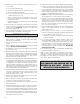
WIRING DIAGRAM All electrical connections should be done by a qualified electrician. NOTE: The extra brown wire on the fan center has no use. It should be capped off or removed. The conduit may be cut shorter to provide a cleaner installation FIREBRICK AND BAFFLE REPLACEMENT FIREBOX BRICK REPLACEMENT BAFFLE/BRICK REPLACEMENT This furnace comes from the factory with the firebrick installed. However, if brick replacement is necessary, follow these instructions.
TESTING AND OPERATING PROCEDURES GENERAL FURNACE OPERATION STARTING A WOOD FIRE When you start a fire in the furnace and it reaches operating temperature, the blower(s) will come on automatically. The snap-disc is adjustable from 100°F(A) to 140°F(E), Each click on the switch is approximately 5°F. It comes from the factory, set at 120°F, setting C. The rocker switch on the top of the junction box gives you the option to run one blower or two.
If the fire goes out or does not hold overnight, look for: 1. Poor draft. 2. Incorrect damper settings. 3. Improper firing methods for coal being used. 4. More combustion air needed. 5. Coal not sized to the furnace. We recommend 1” to 3” diameter pieces of coal. 6. Ashes, if allowed to accumulate in the ash pit, will not allow the passage of required air for combustion. Keep ash pit clean. 7. This furnace is not to be used with an automatic stoker unless so certified.
TROUBLE SHOOTING AND PROBLEM SOLVING 1. Problem: 4. Problem: Smoke puffs from furnace Distribution blower vibrating Solution: Solution: A. Check chimney draft. Check for blocked chimney or flue pipe. Use mirror to check chimney clearance. A. Tighten blower wheel to motor shaft. B. Check for bad fan bearings. B. Check ash pit — if it is too full, empty. 5. Problem: C. Make sure furnace room is not too airtight. Distribution blower continues to run or will not run D.
PARTS DIAGRAM 23 33 32 28 22 34 31 21 20 3 18 19 16 4 17 3 2 1 27 25 26 35 24 9 3 8 7 10 6 14 15 16 17 2 5 3 30 29 13 12 11 12 USSC
PARTS DIAGRAM AND LIST Key Description Part # Qty Key Description Part # Qty 1 Feed Door Assy. (w/Rope Gasket) 69091 1 42 Snap-disc Box 68234 1 2 Door Handle 24179 2 43 Conduit Assembly (1.5ft) 68231 1 N/S Lock Nut, 1/2-13 83444 2 44 Junction Box 25625 1 N/S Washer 83835 2 45 Insulation (5” x 5”) 25626 1 3 Spring Handle 89574 4 46 Junction Box Cover 4 Feed Door Latch 23786 1 47 Rocker Switch 5 Ash Door Assy.
16DIKL FORCED DRAFT BLOWER - OPTIONAL KIT USSC offers a forced induced draft blower kit as an option to upgrade your Clayton furnace. Advantages of the forced draft are quicker recovery and greater turbulence inside the firebox for better mixing of fuel and oxygen. And, it also allows you the furnace to be thermostatically controlled. You may purchase a forced draft kit from your local dealer or direct from U.S. Stove. If installing a 16DIKL, follow the instructions supplied with the kit.
DOMESTIC HOT WATER COIL - OPTIONAL KIT This Furnace will accept the installation of a Domestic Hot Water Coil Kit. The U.S. Stove kit is a 1124 Water Coil and it may be purchased from your local dealer. 2 1. Remove the access panel on the rear of the furnace enclosure. 2. With a utility knife, cut away a section of the insulation (if equipped) directly behind the access panel. 1 3. Remove the cover plate from the rear of the furnace firebox. ACCESS PANEL 4.
BULLETIN RC454 A GUIDE TO BURNING COAL IN YOUR FURNACE Furnaces that are capable of burning coal usually will burn both Bituminous and Anthracite coal. Anthracite is perhaps the best coal fuel because of its long even burn time, high heat output, and cleanliness which make it a good choice for the home. However, keep in mind it is a much more difficult fuel to use, requires more care and patience, is not so widely available, and is usually much more expensive than Bituminous.
BULLETIN RC454 A GUIDE TO BURNING COAL IN YOUR FURNACE When the fire is well established and the room is becoming warm, partially close the dampers. Some experimenting will have to take place with each particular setting of all dampers and controls as the chimney provides the draft necessary to not only exhaust the smoke, but to pull combustion air into the heater as well - and no two chimney’s perform the same.
NOTES 18 USSC
NOTES USSC 19
HOW TO ORDER REPAIR PARTS This manual will help you obtain efficient, dependable service from the furnace, and enable you to order repair parts correctly. Keep this manual in a safe place for future reference. When placing an order or for warranty claims, please provide the following information found on the Certification Plate located below the ash door. PART NUMBER PART DESCRIPTION MODEL NUMBER - 1602M SERIAL NUMBER______________ United States Stove Company 227 Industrial Park Road P.O.