UNITY/I ™ Three-Phase Uninterruptible Power Systems UT340, UT360, UT380, UT3100 60 Hz Planning and Installation Manual LTM-0357A Copyright 1995, Best Power Technology, Inc.
UT340, UT360, UT380, and UT3100 Planning and Installation Manual IMPORTANT SAFETY INSTRUCTIONS SAVE THESE INSTRUCTIONS This manual contains important instructions for your UNITY/I™ UPS. The installation and use of this product must comply with all national, federal, state, municipal, or local codes that apply. If you need help, please call BEST’s Technical Support Center at 1-800-356-5737 (U.S.A. or Canada; elsewhere, call your local BEST office). WARNING! UPS units contain hazardous AC and DC voltages.
UT340, UT360, UT380, and UT3100 Planning and Installation Manual Table of Contents List of Tables and Figures . . . . . . . . . . . . . . . . . . . . . . . . . . . . . . . . . . . . . . . . . . . . . . . ii 100: Introduction . . . . . . . . . . . . . . . . . . . . . . . . . . . . . . . . . . . . . . . . . . . . . . . . . . . . . . . . . . . 1 101: UPS Footprint . . . . . . . . . . . . . . . . . . . . . . . . . . . . . . . . . . . . . . . . . . . . . . . . . . . . .
UT340, UT360, UT380, and UT3100 Planning and Installation Manual List of Tables and Figures Tables 1 2 3 4 5 6 7 8 AC Input Specifications, UT340 and UT360 . . . . . . . . . . . . . . . . . . . . . . . . . . . . . . . . . . . . . 3 AC Output Specifications, UT340 and UT360 . . . . . . . . . . . . . . . . . . . . . . . . . . . . . . . . . . . 3 DC Input/Battery Specifications, UT340 and UT360 . . . . . . . . . . . . . . . . . . . . . . . . . . . . . . 4 General Specifications, UT340 and UT360 . . . . . . .
UT340, UT360, UT380, and UT3100 Planning and Installation Manual Section 100: Introduction An uninterruptible power system (UPS) protects sensitive equipment against unacceptable disturbances from the mains (AC line) supply. The UNITY/I™ three-phase UPS has the capacity to serve a wide variety of electrical equipment— from mainframe computers to enterprise-wide EDP installations to production lines. The UNITY/I three-phase UPS provides true on-line, single-conversion technology and harmonics isolation.
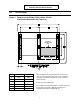
UT340, UT360, UT380, and UT3100 Planning and Installation Manual 101 UPS Footprint Figure 1: Footprint of the UT340, UT360, UT380, UT3100 with Conduit Connection Kit (Top View) CONDUIT CONNECTION BOX CABLE ENTRY Inches Millimeters A 39.4 1000 B 17.9 455 Allow a minimum of 3 feet (914 mm) at the front of the unit, 3 feet (914 mm) at the top of the unit, and 6 inches (152 mm) at the back of the unit for service clearance and for air flow. C 19.8 504 Cable entry from bottom only. D 27.
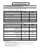
UT340, UT360, UT380, and UT3100 Planning and Installation Manual 102 Specifications for the UT340 and UT360 Tables 1 - 4 contain specifications for UPS models UT340 and UT360.
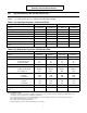
UT340, UT360, UT380, and UT3100 Planning and Installation Manual Table 3: DC Input/Battery Specifications, UT340 and UT360 UT340 UT360 250 kcmil or 2 x 1/0 500 kcmil or 2 x 3/0 Nominal DC current - Amps 200 300 Nominal DC voltage 216 216 Nominal number of cells 108 108 246 246 20 30 91 91 89 86 92 92 90 87 Acceptable external battery cable size range AWG 1 Factory-set float charge voltage 2 Charger current limit - Amps Inverter % efficiency 3 - 100% load - 75% load - 50% load - 25% loa
UT340, UT360, UT380, and UT3100 Planning and Installation Manual 103 Specifications for the UT380 and UT3100 Tables 5 - 8 contain specifications for UPS models UT380 and UT3100.
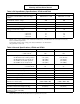
UT340, UT360, UT380, and UT3100 Planning and Installation Manual Table 7: DC Input/Battery Specifications, UT380 and UT3100 UT380 UT3100 250 kcmil or 2 x 1/0 500 kcmil or 2 x 3/0 Nominal DC current - Amps 245 310 Nominal DC voltage 360 360 180 180 410 410 25 30 92 92 90 87 93 93 91 88 Acceptable external battery cable size range - AWG 1 Nominal number of cells Factory-set float charge voltage 2 Charger current limit - Amps 3 Inverter % efficiency - 100% load - 75% load - 50% load - 25
UT340, UT360, UT380, and UT3100 Planning and Installation Manual 104 Receiving and Moving the UPS WARNING! The UPS and related equipment are very heavy. To prevent personal injury or equipment damage, use extreme care when handling and transporting the UPS cabinet and related equipment. 1. While the UPS system is still on the truck, inspect the equipment and shipping container(s) for any signs of damage. Do not install the system if damage is apparent.
UT340, UT360, UT380, and UT3100 Planning and Installation Manual 105 Storing the UPS and Batteries You can store the UNITY/I UPS between -4o and 104o F (-20o and 40o C). However, BEST recommends that the unit and batteries be stored between 59o and 77o F (15o and 25o C). This temperature range or cooler allows batteries to have a longer shelf life. Recharge stored batteries every 90 to 120 days.
UT340, UT360, UT380, and UT3100 Planning and Installation Manual 107 Technical Support Best Power Technology, Incorporated is committed to outstanding customer service. Our Technical Support Center is happy to help you with any problems or answer any questions you may have. A service technician is available 24 hours a day, 365 days a year. Please have the UPS model number and serial number available when you call. See the ID label located inside the front door of the UPS.
UT340, UT360, UT380, and UT3100 Planning and Installation Manual 201 Installing the Maintenance Bypass Cabinet (MBC) and UPS IMPORTANT! If you do not have a BEST maintenance bypass cabinet (MBC), you must provide overcurrent protection and a UPS input AC disconnect means. BEST strongly recommends that a means of bypassing the UPS from the critical load be provided for maintenance.
UT340, UT360, UT380, and UT3100 Planning and Installation Manual Figure 2: Front View (Covers Removed) 11
UT340, UT360, UT380, and UT3100 Planning and Installation Manual Figure 3: UT340 - UT3100 Installation Wiring Diagram, Typical Installation, No External Maintenance Bypass Cabinet ADDITIONAL NOTES: A qualified electrician must install the UPS according to all applicable codes. All power and control wires must be in separate conduits. The grounding electrode conductor (protective earth—PE) must be the same size (ampacity) as the UPS input conductors.
UT340, UT360, UT380, and UT3100 Planning and Installation Manual Figure 4: UT340 and UT360 Installation Wiring Diagram, Typical Installation ADDITIONAL NOTES: A qualified electrician must install the UPS according to all applicable codes. All power and control wires must be in separate conduits. The grounding electrode conductor (protective earth—PE) must be the same size (ampacity) as the UPS input circuit conductors.
UT340, UT360, UT380, and UT3100 Planning and Installation Manual Figure 5: UT380 and UT3100 Installation Wiring Diagram, Typical Installation ADDITIONAL NOTES: A qualified electrician must install the UPS according to all applicable codes. All power and control wires must be in separate conduits. If you do not have a BEST-supplied maintenance bypass cabinet (MBC), you must provide overcurrent protection and UPS input AC disconnect means.
UT340, UT360, UT380, and UT3100 Planning and Installation Manual Figure 6: External Connection Board Use Class 1 wiring methods. 1 NOT USED X001 NOT USED X002 NOT USED X005 NOT USED 3 1 NOT USED X006 3 1 SUMMARY ALARM IF 1-3 CONNECTED 2 X007 3 1 BATTERY OPERATION (30 SECS.
UT340, UT360, UT380, and UT3100 Planning and Installation Manual Figure 7: Communication Interface Board (Option) Use Class 1 wiring methods. Not Used To Controller X002 X001 X003 25 PIN SUB D MALE X004 25 PIN SUB D MALE X005 25 PIN SUB D FEMALE COMMUNICATION INTERFACE BOARD X005 X004 X003 Serial Port RS232 Serial Port 0 - 20 mA current loop RELAY CONTACTS: 30 VAC, 60 VDC Maximum 0.5 A, Minimum 0.
UT340, UT360, UT380, and UT3100 Planning and Installation Manual Figure 8: Relay Board (Option) The relays are shown in the alarm position and correspond to non-energized coils. RELAY BOARD X002:1 2 3 MAINS FAILURE X003:1 2 3 BATTERY CHARGING FAILURE X004:1 2 3 OVERLOAD Description Minimum Maximum Contact voltage - AC 6V 250 V Contact current - AC * 50 mA 8A 6 V / 50 mA 250 V / 0.
UT340, UT360, UT380, and UT3100 Planning and Installation Manual 202 Installing the External Batteries and DC Disconnect (DCD) External batteries must be installed and connected to the UPS by a qualified service person who is familiar with UPS battery installations and applicable building and electrical codes. The qualified service person should read this entire section before the UPS and batteries arrive. DANGER! Full voltage and current are always present at the battery terminals.
UT340, UT360, UT380, and UT3100 Planning and Installation Manual DANGER! 6. Do not connect the battery terminal to ground (earth). If any battery terminal is inadvertently grounded, remove the source of the ground. Contacting any part of a grounded battery can cause a risk of electric shock. 7. To reduce the risk of fire or electric shock, install the batteries in a temperature and humidity controlled indoor area, free of contaminants. 8.
UT340, UT360, UT380, and UT3100 Planning and Installation Manual Clean the cables and battery terminals before making the battery connections. Apply a thin coating of conductive grease before making the battery connections, or apply petroleum jelly to the entire connection after it has been made. Torque battery connections to the battery manufacturer’s specifications. Follow the steps below and any instructions provided with the battery system: 1. 2. Connect the cables between batteries. a.
UT340, UT360, UT380, and UT3100 Planning and Installation Manual 5. Check the DC voltage. a. Connect the DC fuse(s) as shown in the battery installation diagram provided with the batteries. Verify proper voltage and polarity at the battery pack. See Table 3 in Section 102 or Table 7 in Section 103 for nominal DC voltage. b. Turn the DC disconnect (DCD) “ON.” c. Meter for proper nominal DC voltage at the UPS end of the cables.
UT340, UT360, UT380, and UT3100 Planning and Installation Manual Dispose of Batteries Properly: For assistance, call BEST’s Technical Support Center at 1-800-356-5737 (U.S.A. or Canada) or call your local BEST office. WARNING! Do not dispose of batteries in a fire because the batteries could explode. Do not open or mutilate batteries. Released electrolyte is harmful to the skin and eyes and may be toxic. Batteries contain lead.
UT340, UT360, UT380, and UT3100 Planning and Installation Manual 301 Initial Startup and Phase Check for Units with a BEST-Supplied Rotary Switch MBC Follow this Procedure Exactly! No Load Should Be Connected! 1. Make sure that all AC and DC power is off. 2. Switch the UPS bypass switch to “UPS.” 3. Make sure that the main circuit breaker in the load panel is off so that the loads cannot receive power from the UPS. 4.
UT340, UT360, UT380, and UT3100 Planning and Installation Manual CAUTION Before you switch the UPS bypass switch from “UPS” to “LINE”, use the steps below to check for correct voltage, phasing, and system operating mode. 12. Program the unit into static bypass operation: a. Press to access the user parameters. b. Press the c. Press to turn static bypass operation on. The display should show Bypass operation. or key until the display shows Bypass operation: OFF. 13.
UT340, UT360, UT380, and UT3100 Planning and Installation Manual 15. At the maintenance bypass cabinet (MBC), measure the following: a. b. c. N input to Ground N output to Ground N input to N output _______VAC _______VAC _______VAC “N input to N output” should not exceed “N input to Ground.” If it does, call BEST’s Technical Support Center. 16. Check for proper voltages at the bypass switch load output terminals and the load distribution panel(s). a. b. c.
UT340, UT360, UT380, and UT3100 Planning and Installation Manual 302 Initial Startup and Phase Check for Units with a BEST-Supplied Three-Breaker MBC Follow this Procedure Exactly! No Load Should Be Connected! 1. Make sure that all AC and DC power is off. 2. Switch the maintenance bypass breaker (MBB) “OFF.” 3. Switch the UPS output breaker (UOB) “OFF.” 4. At the mains AC input panel, switch on the input power to the UPS and maintenance bypass cabinet (MBC). 5.
UT340, UT360, UT380, and UT3100 Planning and Installation Manual CAUTION Before you switch the maintenance bypass breaker (MBB) “ON,” use the steps below to check for correct voltage, phasing, and system operating mode. 12. Program the unit into static bypass operation: a. Press to access the user parameters. b. Press the c. Press to turn static bypass operation on. The display should show Bypass operation. or key until the display shows Bypass operation: OFF. 13.
UT340, UT360, UT380, and UT3100 Planning and Installation Manual 16. At the maintenance bypass cabinet (MBC), measure the following: a. b. c. N input to Ground N output to Ground N input to N output ______VAC ______VAC ______VAC “N input to N output” should not exceed “N input to Ground.” If it does, call BEST’s Technical Support Center. 17. Check for proper voltages at the maintenance bypass cabinet (MBC) load output terminals and the load distribution panel(s). a. b. c.
UT340, UT360, UT380, and UT3100 Planning and Installation Manual Section 400: Clearing the Events Log The events log contains the 250 most recent UPS events, including alarms. To clear the events log, follow the steps below: 1. Simultaneously press and . The display should show Key in password. 2. Using the key pad, enter “920701.” The display should show Logging stack is reset. The events log is now cleared. 3. Press . The display should show Normal operation load power xx%.
UT340, UT360, UT380, and UT3100 Planning and Installation Manual 501 1. Shutdown Procedure for Units with a BEST-Supplied Rotary Switch MBC If you have shut the loads down: Skip to step 3. If the loads are to remain powered: Program the unit into static bypass operation: a. Press to access the user parameters. b. Press the c. Press to turn static bypass operation on. The display should show Bypass operation. or key until the display shows Bypass operation: OFF. 2.
UT340, UT360, UT380, and UT3100 Planning and Installation Manual 2. Switch the maintenance bypass breaker (MBB) “ON.” 3. Switch the UPS output breaker (UOB) “OFF.” 4. Press the red “off” button located inside the UPS front door. 5. Switch the UPS input breaker (UIB) “OFF.” 6. Switch the DC disconnect (DCD) “OFF.” 7. Turn the pre-charge/discharge switch to the discharge position and hold it until the LED turns off. The UPS display should now be blank.
UT340, UT360, UT380, and UT3100 Planning and Installation Manual 3. Within 20 seconds, the UPS display should show **Stand-by**. 4. Turn the pre-charge/discharge switch to the pre-charge position and hold it until the LED turns off. 5. Switch the DC disconnect (DCD) “ON.” 6. Press the green “on” button located inside the front door of the UPS. The UPS display should show Normal operation load power xx%. 7. Program the unit into static bypass operation: a. Press to access the user parameters. b.
UT340, UT360, UT380, and UT3100 Planning and Installation Manual 4. Turn the pre-charge/discharge switch to the pre-charge position and hold it until the LED turns off. 5. Switch the DC disconnect (DCD) “ON.” 6. Press the green “on” button located inside the UPS front door. The UPS display should show Normal operation load power xx%. 7. Program the UPS into static bypass operation: a. Press to access the user parameters. b. Press the c. Press to turn bypass operation on.
UT340, UT360, UT380, and UT3100 Planning and Installation Manual Ground (Earth): A conducting connection, whether intentional or accidental, by which an electric circuit or equipment is connected to earth or to some conducting body that serves in place of earth. Load tolerance - symmetrical: Equally balanced loads on a three-phase system. Load tolerance - asymmetrical: Unbalanced loads on a three-phase system.