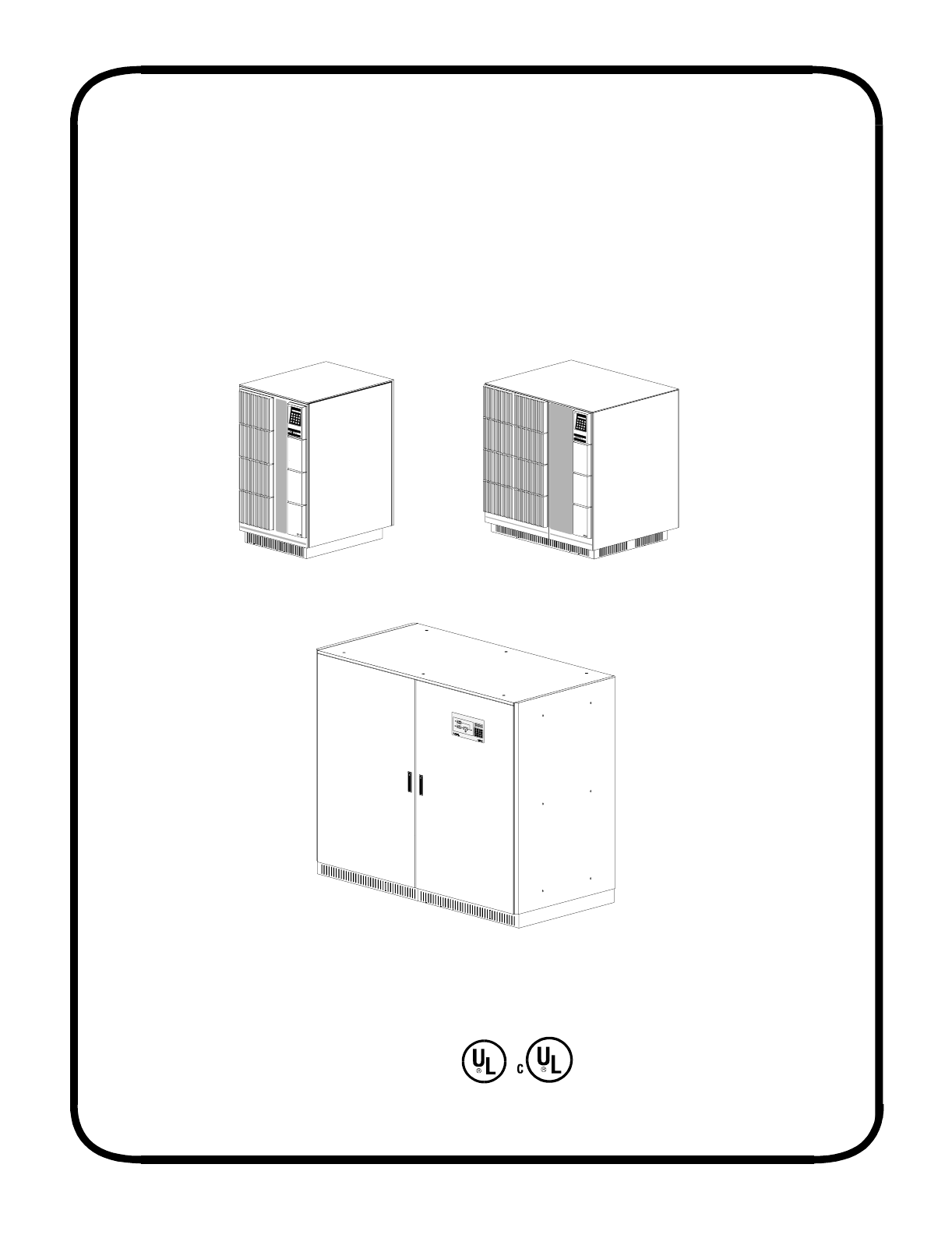
UNITY/I™ Three-Phase Uninterruptible Power Systems Sistemas de suministro ininterrumpido de energía trifásica User Manual/Manual del Usuario UT310 and UT315 UT320, UT330, UT340, UT360, UT380 and UT3100 UT3120, UT3160 and UT3220 60 Hz Models have these listings: Los modelos de 60 Hz apparecen en las siguientes listas: FSS-0370F Copyright 1995, 1996, Best Power. All rights reserved. Todos los derechos reservasos.
English . . . . . . . . . . . . . . . . . . . . . . . . . . . 1 Español . . . . . . . . . . . . . . . . . . . . . . . . .
TABLE OF CONTENTS Introduction . . . . . . . . . . . . . . . . . . . . . . . . . . . . . . . . . . . . . . . . . . . . . . . . . . . . . . . . . . . . 3 001 Storing the UNITY/I and Batteries . . . . . . . . . . . . . . . . . . . . . . . . . . . . . . . . . 3 002 If You Have A Question . . . . . . . . . . . . . . . . . . . . . . . . . . . . . . . . . . . . . . . . . 3 Section 100: Startup and Shutdown . . . . . . . . . . . . . . . . . . . . . . . . . . . . . . . . . . . . . . . . . .
IMPORTANT SAFETY INSTRUCTIONS SAVE THESE INSTRUCTIONS This manual contains important instructions for your UNITY/I™ UPS. IF THE UPS IS SOUNDING AN ALARM, go to Section 206. To silence the audible alarm, press the silence alarm key shown at the right. If you do not silence the alarm, it will automatically silence itself after 30 seconds. Silencing the audible alarm does not correct the problem that caused the alarm.
INTRODUCTION An uninterruptible power system (UPS) protects sensitive equipment against unacceptable disturbances from the mains (AC line) supply. The UNITY/I™ Three-Phase UPS has the capacity to serve a wide variety of electrical equipment — from mainframe computers to enterprise-wide EDP installations to production lines. The UNITY/I Three-Phase UPS provides true on-line, singleconversion technology and harmonics isolation.
SECTION 100: STARTUP AND SHUTDOWN CAUTION! To avoid possible personal injury or equipment damage, assume that there may be AC voltage at the UPS’s output terminals / receptacles any time AC input power or DC battery voltage is applied. The UPS can provide output voltage from the batteries even when there is no AC input line voltage. When AC voltage is present, the UPS can provide output voltage even when the batteries are disconnected.
SECTION 200: OPERATION 201 The Display Unit The display unit on the front of the UPS includes a display, an alarm LED, and a keypad to help you communicate with the UPS and to help the UPS notify users of operating conditions. Figure 1 below shows the display unit for the UT310 through UT3100. Figure 2 on the next page shows the display unit for the UT3120 through UT3220. Figure 3 on page 7 shows the optional LED panel that is available for the UT3120 through UT3220.
DISPLAY ALARM LED ALARM KEYPAD 0 Figure 2: Standard Display Unit for the UT3120, UT3160, and UT3220 6
An optional LED panel (shown below) is available for the UT3120, UT3160, and UT3220. This panel gives you information about the unit’s operation modes and about the cause of alarms. The drawing below shows the panel and points out each LED (light) on the panel. Table 1 explains what each LED means when it is green and what it means when it is red.
202 Operating Modes The UNITY/I display automatically shows the mode the unit is operating in. Table 2 below shows sample displays and explains what they mean. TABLE 2 - Operating Modes Mode Displayed (Sample Display) What It Means Normal operation load power ##% The UPS is in the normal operation mode. During normal operation, mains (AC line) passes through the UPS and out to the load. The unit’s inverter regulates the output and charges the batteries.
203 Using the Keys Key What It Does Key Scrolls up through lists such as the parameters, the alarm log, or the events log. See Sections 205, 207, and 208. What It Does Displays the time and date. If the unit is in parameter mode, this key changes the setting of a parameter from “OFF” to “ON.” See Section 205. Scrolls down through lists such as the parameters, the alarm log, or the events log. See Sections 205, 207, and 208. Displays inverter current. See Section 204. Displays output frequency.
204 Displaying Measurements As it operates, the UNITY/I measures several values that you can display by pressing one or two keys. This section shows you what keys to press to display the measurements, what a sample display of each measurement looks like, and what the displays mean. If two keys are shown, press them at the same time. The display values shown below are samples that are typical for some 60 Hz models. Actual values vary depending on the unit’s size, frequency, and voltage.
When two keys are shown, press them at the same time. Keys Sample Display What the Display Means 50 Hz Models Only: 50 Hz Models Only. Mains 2. voltage Bypass mains voltage is 3 x 385 VAC (if 385 385 385 the bypass mains option is installed). Battery temp. 25 C Battery temperature is 25 C (77 F) (This display is only for units with battery temperature compensation.
TABLE 3 - User Parameters PARAMETERS FACTORY SETTING COMMENTS Second Language OFF If you select ON, the UNITY/I displays all messages in its second language. (For 60 Hz systems, this language is Spanish.) The following languages are available, but they must be ordered from the factory: Danish, Dutch, Finnish, French, German, Italian, Polish, and Portuguese. Adaptive slewrate ON OFF is used when mains frequency (AC input frequency) is unstable. Phone BEST before changing this parameter.
206 Alarms The UNITY/I is designed to alert you to certain UPS conditions. If the unit detects an alarm condition, it: • lights the red alarm light in the upper left corner of the display unit, and • sounds a 30-second audible alarm. To silence the audible alarm, press this key: If you do not silence the alarm, it will silence itself after 30 seconds. Silencing the audible alarm does not correct the condition that caused the alarm.
TABLE 4 - Alarm List Alarm Message What It Means What to Do The DC disconnect circuit breaker is open. If bypass voltage is within tolerance (see Glossary), the unit transfers to static bypass operation. If not, the unit transfers to standby and does not supply output voltage. At the DC disconnect, you must first turn the precharge/discharge switch to the precharge position and hold it until the LED turns off. Precharge is very important to prevent damage to your equipment.
Alarm Message What It Means What to Do Fan fault If the fan monitoring option is installed, this alarm sounds if one or more of the fans are slowing down. The unit’s status does not change, but the problem may cause other high-temperature alarms that could change the unit’s status. Phone BEST’s Worldwide Service. Fatal Error RAM1 data error Components on the main controller board have failed. Phone BEST’s Worldwide Service. Fault in int.
Alarm Message What It Means What to Do High temp. transformer The temperature in the main transformer is too high. If the problem is not corrected soon, the unit will transfer to standby and will not supply output voltage. Find the exhaust vents for the UPS fans and check to see if the fans are operating. Do not try to open the unit, and do not insert anything into a fan vent. If the fans are not operating, call BEST’s Worldwide Service.
Alarm Message What It Means What to Do Mains freq. is out of tolerance The mains (AC input) frequency is out of tolerance (see the Glossary). The unit transfers to battery operation. If mains frequency comes back within tolerance, the unit transfers back to normal operation. If not, the unit continues to run on battery until “Low DC shutdown.” Then, if bypass is within tolerance, the unit transfers to bypass. If not, the unit transfers to standby and does not supply output voltage.
Alarm Message Output is out of tolerance What It Means What to Do The output voltage is too high or too low (out of tolerance). If the alarm was caused by high output voltage, the unit transfers to static bypass operation if bypass is within tolerance. If bypass is not within tolerance, the unit transfers to standby and does not supply output voltage. If the UPS is in standby, restart the UPS by pressing the green button inside the door.
Alarm Message Static switch 2 temp. shutdown Static switch 2 temp. warning What It Means What to Do The temperature on the heatsink for the bypass static switch is higher than the shutdown level and the bypass static switch has opened. The unit switches to battery operation until the temperature falls below the shutdown level; then, it transfers back to normal operation. If the temperature does not fall to this level before the Low DC shutdown, there will be no output to the load equipment.
Alarm Message What It Means What to Do TSM 1 temp. shutdown Inverter module 1 has shut down because the temperature on the heatsink is higher than the shutdown level. If bypass is within tolerance, the unit transfers to static bypass operation. If not, the unit transfers to standby mode and does not supply output voltage. Find the vents for the UPS fans and check to see if the fans are operating. Do not try to open the unit, and do not insert anything into a fan vent.
Alarm Message What It Means What to Do TSM 3 temp. shutdown Inverter module 3 has shut down because the temperature on the heatsink is higher than the shutdown level. If bypass is within tolerance, the unit transfers to static bypass operation. If not, the unit transfers to standby and does not supply output voltage. Find the vents for the UPS fans and check to see if the fans are operating. Do not try to open the unit, and do not insert anything into a fan vent.
208 Displaying the Events Log The events log is a list of the last 250 alarms and operational modes. This log includes the time and date of each event. Most entries in this log will be alarms; see Section 206 for explanations of the alarms. Other entries describe operating modes; the table below lists these mode messages and explains what they mean. TABLE 5 - Log Messages Mode What It Means Main processor unit (MPU) is reset The UPS was completely switched off. Stand-by The UPS was in standby mode.
SECTION 300: PREVENTIVE MAINTENANCE BEST recommends a periodic preventive maintenance check every six months. BEST also recommends that the cooling fans and batteries be replaced every three years. 301 Preventive Maintenance Check At the preventive maintenance check, a qualified service technician should: • Check all wiring connections. • Inspect and clean the unit. • Check the batteries. • Check the AC and DC meter functions. • Perform a battery capacity or battery monitor test. (See Sections 302 and 303.
To perform a battery monitor test: 1. Press to display the user parameters. 2. Press or 3. Press to start the battery monitor test. The display shows “Batt. operation time > xxx min.” to scroll through parameters until the display shows “Battery monitor test.” (“xxx” = the minutes of runtime remaining. This number will fluctuate during the test.) 4. When the test is complete, the display shows “Normal operation load power xx%” if the batteries are in acceptable condition.
4. If you wish to abort the test while it is underway, follow these steps: a. Display the user parameter list by pressing . b. Use the arrow keys to scroll through the parameters until the display shows “Battery capacity test: xxx.” c. Switch the battery capacity test “OFF” by pressing . 5. Wait until the display shows “Normal operation load power xx%” and a short alarm sounds. 6. Press . The display will show “Battery capacity test: xxx.” (“xxx” = the estimated backup time in minutes) 7.
SECTION 400: SPECIFICATIONS For a complete list of specifications, see the Planning and Installation Manual for your model. TABLE 6 - General specifications for all models (unless otherwise noted) Mains tolerance +10%, 15% (programmable) Bypass tolerance ±10% (programmable) Input frequency ±6% (programmable) 60 Hz or 50 Hz. Output frequency 60 Hz ±6% or 50 Hz ±6%. 60 Hz ±0.1% or 50 Hz ±0.1%.
SECTION 500: OPTIONS BEST offers many options for UNITY/I units. For more information, contact your local BEST office (see the inside front cover) or your dealer. Note that some options only apply to certain models. Battery Temperature Compensation: Enables the UPS to adapt the charging voltage to the battery temperature. This is standard in units with internal batteries but optional for units with external batteries.
Warranties: In addition to the standard warranty on page 28, BEST offers a large array of service plans and extended warranties to fit your needs. Whether you choose a basic level or one that makes power protection virtually effortless, you can be sure Best Power will honor its commitment to provide you with true peace of mind. Contact your local Best Power representative for availability in your country. By calling us toll-free at 1-800-356-5737 (U.S.
SECTION 600: WARRANTY LIMITED TWO YEAR WARRANTY Standard Warranty For All Purchases BEST POWER (an Invensys company) warrants that each product sold by BEST POWER is compatible with existing commercially available computer equipment with enclosed power supplies and is free from defects in materials and workmanship under normal use and service. This warranty is applicable only to the initial retail purchaser (PURCHASER), and is not transferable.
SECTION 700: GLOSSARY Ampere (Amp): A unit of electric current. One amp = a steady current produced by one volt applied across a resistance of one ohm. British thermal unit (BTU): A unit of heat energy. One BTU = the heat needed to raise the temperature of one pound of air-free water from 60 F (15.5 C) to 61 F (16.1 C) at a constant pressure of one standard atmosphere.
For Users in the United States Only This equipment has been tested and found to comply with the limits for a Class A digital device, pursuant to Part 15 of the FCC rules. These limits are designed to provide reasonable protection against harmful interference when the equipment is operated in a commercial environment.
INSTRUCCIONES DE SEGURIDAD IMPORTANTES CONSERVE ESTAS INSTRUCCIONES Este manual contiene instrucciones importantes para su UNITY/I UPS. SI EL UPS ACTIVA UNA ALARMA, consulte la Sección 206. Para detener la alarma sonora, pulse la tecla que aparece a la derecha. Si el usuario no silencia la alarma, ésta se detendrá automáticamente al cabo de 30 segundos. El silenciar la alarma no corrige el problema que la originó.
INDICE DE MATERIAS Introducción . . . . . . . . . . . . . . . . . . . . . . . . . . . . . . . . . . . . . . . . . . . . . . . . . . . . . . . . . . . . . . . . . 34 001 Almacenamiento del UNITY/I y de las baterías . . . . . . . . . . . . . . . . . . . . . . . . . . . . 34 002 Si tiene alguna pregunta . . . . . . . . . . . . . . . . . . . . . . . . . . . . . . . . . . . . . . . . . . . . . . 34 Sección 100: Arranque y apagado . . . . . . . . . . . . . . . . . . . . . . . . . . . . . . . . . . . . . . . . .
INTRODUCCION Los sistemas de suministro ininterrumpido de energía (UPS) protegen al equipo sensible contra perturbaciones inaceptables provenientes del suministro de la línea principal (línea de CA.) El UPS trifásico UNITY/I posee la capacidad para servir a una gran variedad de equipos eléctricos, desde macrocomputadoras e instalaciones para procesamiento de datos electrónicos (EDP) de empresas a líneas de producción.
SECCION 100: ARRANQUE Y APAGADO ¡PRECAUCION! Para evitar posibles lesiones a personas o daños a los equipos, presuponga que puede haber voltaje de CA en los terminales de salida o receptáculos del UPS cada vez que se aplique alimentación CA o voltaje de CC de batería. El UPS puede proporcionar voltaje de salida proveniente de las baterías aun cuando no haya voltaje de alimentación de CA. Cuando hay voltaje de CA, el UPS puede proporcionar voltaje de salida incluso si las baterías están desconectadas.
SECCION 200: OPERACION 201 La unidad de visualización La unidad de visualización en la parte delantera del UPS incluye una pantalla, un diodo LED de alarma y un teclado que le permitirá comunicarse con el UPS y que a la vez servirá para que el UPS notifique a los usuarios las condiciones de funcionamiento. En la figura 1 aparecen las unidades de visualización del UT310 al UT3100. En la figura 2 de la página siguiente aparecen las unidades de visualización del UT3120 al UT3220.
PANTALLA DIODO LED DE ALARMA ALARM TECLADO 0 Figura 2: Unidad estándar de visualización para los modelos UT3120, UT3160, y UT3220 37
Los modelos UT3120, UT3160, y UT3220 cuentan con un panel de diodos LED opcional (que aparece a continuación), el cual proporciona información acerca de los modos de operación de la unidad y acerca de la causa de las alarmas. El diagrama que aparece a continuación muestra el panel y señala cada diodo LED (luz) del panel. En la tabla 1 se explica lo que indica cada diodo LED cuando está verde y cuando está rojo.
202 Modos de funcionamiento La pantalla del UNITY/I muestra automáticamente el modo en el que la unidad está funcionando. En la tabla 2 que aparece a continuación aparecen pantallas de muestra y se explica lo que significan. TABLA 2 - Modos de operación Modo visualizado (Pantalla de muestra) Significado Normal operation load power ##% El UPS está en el modo de operación normal. Durante el funcionamiento normal, la línea principal (línea de CA) pasa a través del UPS y sale hacia la carga.
203 Uso de las teclas Tecla Acción Tecla Acción Sube por listas tales como parámetros, el registro de alarmas, o el registro de eventos. Consulte las secciones 205, 207 y 208. Visualiza la hora y la fecha. Si la unidad está en el modo de parámetro, esta tecla cambia el ajuste de un parámetro de “OFF” (APAGADO) a “ON” (ENCENDIDO.) Consulte la sección 205. Baja por las listas tales como parámetros, el registro de alarmas, o el registro de eventos. Consulte las secciones 205, 207 y 208.
204 Visualización de las mediciones A medida que funciona, el UNITY/I mide diversos valores que se pueden visualizar pulsando una o dos teclas. En esta sección se indican las teclas que se deben pulsar para visualizar las mediciones, aparece una pantalla de muestra de cada medición, y se explica el significado de las pantallas. Si aparecen dos teclas, púlselas al mismo tiempo. Los valores de pantalla que aparecen a continuación son muestras típicas de algunos modelos de 60 Hz.
Cuando aparezcan dos teclas, púlselas al mismo tiempo. Teclas Pantalla de muestra Significado de la pantalla 50 Hz Models Only: Sólo modelos de 50 Hz: Mains 2. voltage El voltaje de la línea principal de bypass es de 385 385 385 3 x 385 VCA (si es que está instalada la opción línea principal de bypass.) Battery temp. 25 C La temperatura de la batería es de 25 C (77 F) Output peak curr 19 19 19 Aac La corriente máxima de salida es de 3 x 19 ACA.
TABLA 3 - Parámetros del usuario PARAMETROS Second Language (Segundo idioma) Adaptive slewrate (Variación de tensión adaptable) AJUSTE DE FABRICA COMENTARIOS OFF Si se selecciona ON (ENCENDIDO), el UNITY/I visualiza todos los mensajes en su segundo idioma (para sistemas de 60 Hz, el idioma es español.) Están disponibles los siguientes idiomas, pero se deben solicitar a la fábrica: danés, holandés, finlandés, francés, alemán, italiano, polaco y portugués.
206 Alarmas El UNITY/I está diseñado para avisar de algunos estados del UPS. Si la unidad detecta una condición de alarma: • encenderá una luz de alarma roja en la esquina superior izquierda de la unidad de visualización y • sonará una alarma de 30 segundos. Para silenciar la alarma, pulse esta tecla: Si el usuario no silencia la alarma, ésta se detendrá automáticamente al cabo de 30 segundos. El silenciar la alarma no corrige el problema que la originó.
TABLA 4 - Lista de alarmas Mensaje de alarma Significado Lo que se debe hacer El cortacircuito de desconexión de CC está abierto. Si el voltaje de bypass está dentro de la tolerancia (consulte el glosario), la unidad conmutará a operación de bypass estático. Si no es así, la unidad conmutará al modo de espera y no suministrará voltaje de salida.
Mensaje de alarma Significado Lo que se debe hacer External service switch activated El interruptor de bypass de servicio externo está en la posición de línea. La unidad está en el modo de espera y no suministra voltaje de salida. Sin embargo, las cargas pueden estar recibiendo energía desde el bypass manual externo. Llame al Worldwide Service de BEST. Fan fault Si está instalada la opción de vigilancia del ventilador, esta alarma sonará si uno o más de los ventiladores están bajando de velocidad.
Mensaje de alarma Significado Lo que se debe hacer High temp. choke La temperatura en el reductor principal es demasiado alta. Si el problema no se corrige con prontitud, la unidad conmutará a operación con batería. Encuentre los orificios de escape de los ventiladores del UPS y vea si éstos últimos están funcionando. No intente abrir la unidad ni introducir nada en los orificios del ventilador. Si los ventiladores no están funcionando, llame al Worldwide Service de BEST. High temp.
Mensaje de alarma Significado Lo que se debe hacer El UPS ha estado funcionando con energía de batería durante un cierto período debido a una interrupción de la energía o a problemas en la entrada de CA. El voltaje de batería ha disminuido al valor prefijado de la alarma de advertencia. Si el UNITY/I está funcionando con batería, el estado de la unidad no variará, pero el voltaje de batería finalmente disminuirá al valor prefijado de apagado.
Mensaje de alarma OFF Button Pushed Significado Lo que se debe hacer Un usuario pulsó el botón rojo “Off” (APAGADO) o habilitó una desactivación de emergencia de la energía. La unidad cambiará al modo de espera y no suministrará voltaje de salida. Vuelva a arrancar la unidad pulsando el botón verde ubicado tras la puerta. Si la unidad no arranca, la alarma fue causada por una desactivación de emergencia (EPO.
Mensaje de alarma Significado Lo que se debe hacer Overload load is over 100% La unidad está cargada con una carga superior a la nominal en una o más fases. El estado del UPS no varía hasta que no pueda mantener el voltaje de salida correcto. Luego la unidad conmutará a operación de bypass estático, siempre y cuando el bypass esté dentro de la tolerancia.
Mensaje de alarma Static switch 2 temp. warning Synchronization error (Esta alarma es normal durante una interrupción de la energía). Significado Lo que se debe hacer La temperatura del disipador térmico para el interruptor estático de bypass es superior al valor prefijado de advertencia. El estado de la unidad no varía. Sin embargo, si la temperatura continúa aumentando, la unidad activará una alarma sonora de “Static switch 2 temp. shutdown” (Apagado por temperatura de interruptor estático 2).
Mensaje de alarma Significado Lo que se debe hacer TSM 1 temp. warning La temperatura del disipador térmico para el módulo 1 del inversor ha sobrepasado el valor prefijado de advertencia. El estado de la unidad no varía. Sin embargo, si la temperatura continúa aumentando, la unidad activará una alarma sonora de “TSM 1 temp. shutdown” (Apagado por temperatura del TSM 1). Encuentre los orificios de los ventiladores del UPS y vea si estos últimos están funcionando.
Mensaje de alarma Significado Lo que se debe hacer TSM 3 temp. warning La temperatura del disipador térmico para el módulo 3 del inversor es superior al valor prefijado de advertencia. El estado de la unidad no varía. Sin embargo, si la temperatura continúa aumentando, la unidad activará una alarma sonora de “TSM 3 temp. shutdown” (Apagado por temperatura del TSM 3). Encuentre los orificios de los ventiladores del UPS y vea si estos últimos están funcionando.
208 Visualización del registro de eventos El registro de eventos es una lista de las últimas 250 alarmas y modos de operación. Este registro incluye la fecha y hora de cada evento. La mayoría de las entradas de este registro son alarmas; consulte la sección 206 para ver la explicación de las alarmas. Las otras entradas describen los modos de operación; en la siguiente tabla aparece una lista de los mensajes de modos y se explica su significado.
SECCION 300: MANTENIMIENTO PREVENTIVO BEST recomienda efectuar una revisión de mantenimiento preventivo cada seis meses, además recomienda reemplazar los ventiladores de enfriamiento y las baterías cada tres años. 301 Revisión de mantenimiento preventivo En la revisión de mantenimiento preventivo, el técnico de servicio calificado deberá: • Revisar todas las conexiones de cableado. • Revisar y limpiar la unidad. • Revisar las baterías. • Revisar las funciones del medidor de CA y CC.
prueba del monitor de batería automáticamente en forma periódica (cada 90 días, por omisión), llame a la oficina de BEST más cercana para obtener mayor información. Nota: La información programada en la unidad se basa en el tamaño y el tipo de baterías que se instalaron cuando se vendió la unidad. Si cambia la configuración de la batería, esta prueba no será exacta para la nueva configuración. Llame a la oficina de BEST más cercana para obtener mayor información.
Para llevar a cabo la prueba de capacidad de batería, siga los siguientes pasos: 1. Pulse 2. Pulse para visualizar los parámetros del usuario. o para desplazarse por los parámetros hasta que en la pantalla aparezca: Battery capacity test: xxx (Prueba de capacidad de batería: xxx) (“xxx” = el tiempo de respaldo desde la última prueba.) Si la prueba nunca se ha efectuado antes o si se abortó, en la pantalla aparecerá “???”. 3. Pulse para abortar la prueba o para continuar.
304 Interruptor de bypass interno (sólo modelos de 50 Hz) Los modelos UT310-UT3100 de 50 Hz vienen con un interruptor de bypass interno tras la puerta delantera. Este interruptor no es el método recomendado de bypass para el UPS si la unidad está en mantenimiento. Use un interruptor de bypass externo de mantenimiento para aislar el UPS en un 100%.
SECCION 400: ESPECIFICACIONES En el Manual de Planificación e Instalación de su modelo encontrará una lista completa de especificaciones. TABLA 6 - Especificaciones generales para todos los modelos (a menos que se especifique lo contrario) Tolerancia de la línea principal +10%, 15% (programable) Tolerancia del bypass ±10% (programable) Frecuencia de entrada ±6% (programable) 60 Hz o bein 50 Hz. Frecuencia de salida 60 Hz ±6% o bein 50 Hz ±6%. 60 Hz ±0.1% o bein 50 Hz ±0.1%.
SECCION 500: OPCIONES BEST ofrece muchas opciones para las unidades UNITY/I. Para obtener mayor información, comuníquese con la oficina local de BEST (consulte la contraportada) o a su distribuidor. Observe que algunas opciones sólo corresponden a algunos modelos. Compensación de la temperatura de la batería: Permite que el UPS adapte el voltaje de carga a la temperatura de la batería.
Garantía: Además de la garantía estándar de la página 62, BEST ofrece una gran variedad de planes de servicio y garantías extendidas según sus necesidades. Si ha escogido un nivel básico o uno que cubra prácticamente todas sus necesidades de protección de energía, puede estar seguro de que Best Power se complacerá en brindarle el mejor servicio. Comuníquese con su representante local de Best Power para ver la disponibilidad de productos en su país. Si nos llama sin costo al 1-800-356-5737 (EE.UU.
SECCION 600: GARANTIA GARANTIA LIMITADA DE DOS AÑOS Garantía estándar para todas las compras BEST POWER (un Invensys sociedad) garantiza que los productos vendidos por BEST POWER son compatibles con los equipos de computación disponibles en el comercio con suministros de energía incorporados, y que carecerán de defectos de materiales y de mano de obra, si es que se les da un uso y servicio normales. Esta garantía sólo es válida para el comprador al por menor (COMPRADOR), y es instransferible.
SECCION 700: GLOSARIO Amperio (amp): Es una unidad de corriente eléctrica. Un amperio equivale a una corriente estable producida por un voltio aplicado a una resistencia de un ohmio. Atenuación de ruido - Modo común: Es la capacidad para atenuar (reducir) el ruido, de la línea a tierra y del cable neutro a tierra. Atenuación de ruido - Modo diferencial: Es la capacidad para atenuar (reducir) el ruido, de línea a línea. Bypass estático: Es un modo de bypass estático dentro de la unidad.
Sólo para usuarios en los Estados Unidos Este equipo ha sido probado y se ha determinado que cumple con los límites de un dispositivo digital clase A, según el artículo 15 de las reglas de la Comisión Federal de Comunicaciones (FCC.) Estos límites tienen como objetivo proporcionar protección razonable contra interferencia dañina cuando el equipo sea operado en un ambiente comercial.