
Datasheet

UNIVER GROUP
4
4
4
4
4
Subject to change
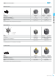
HZE Air Treatment Units
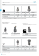
Regulator
Part No.
Connections
Nominal fl ow rate (Nl/min)
(A)
Max inlet pressure (bar-MPa-psi)
Pressure adjustment-relieving version (bar)
Pressure gauge (standard supplied)
Pressure gauge adaptor
0
HZE0R08GM
G1/4
1000
10 - 1 - 145
0,5 ÷ 8,5
HZ9464G
G1/8
(B)
1
2100
10 - 1 - 145
0,5 ÷ 8,5
HZ9464G
G1/8
(C)
2
HZE2R15GM
G1/2
4300
10 - 1 - 145
0,5 ÷ 8,5
HZ9464G
G1/8
(C)
Size
HZE1R10GM
G3/8
HZE1R15GM
G1/2
(A) = Inlet pressure 7 bar, outlet pressure 5 bar - Δp 1 bar
(B) = Upon request (replace HZ9464G gauge with HZE7Z480 square adaptor G1/8, to be ordered separately)
(C) = Standard supplied (replace HZ9464G gauge with HZE7Z480 square adaptor G1/8 placed on the rear side)
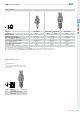
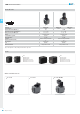
Lubricator
Part No.
Connections
Nominal fl ow rate (Nl/min)
(A)
Max inlet pressure (bar-MPa-psi)
Bowl capacity (cm
3
)
Recommended oil
Min. working fl ow rate (Nl/min)
0
HZE0L08G
G1/4
1400
10 - 1 - 145
20
ISO VG 32
25
1
4400
10 - 1 - 145
85
ISO VG 32
30
2
HZE2L15G
G1/2
7000
10 - 1 - 145
170
ISO VG 32
65
Size
HZE1L10G
G3/8
HZE1L15G
G1/2
(A) = Inlet pressure 7 bar - Δp 0,5 bar
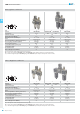
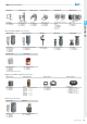
Other available versions
Size Part No.
1
2
HZE1RL10GM - HZE1RL15GM
HZE2RL15GM
Lock not included
Size Part No.
0
Size Part No.
0
1
2
Lockable knob size 1-2Without manometer size 0 Check valve size 0-1-2
HZE0R08G
The check valve inside the regulator allows to relieve downstream
pressure in a quick and e ective way.
HZE0R08GMV
HZE1R10GMV-HZE1R15GMV
HZE2R15GMV