
Installation guide


PAG.
3
English
rev 1.1
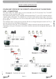
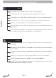
Example 1 – Basic System
Example 2 – DISEqC switches
Example 3 – Combined with terrestrial
Example 4 – Motorized system
QUICK INSTALLATION GUIDE
FOLLOW NEXT STEPS FOR THE CORRECT INSTALLATION OF THIS RECEIVER.
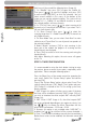
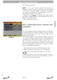
STEP 1: CONNECTIONS
The coaxial cable, with satellite signal, must be connected to the “IF IN” connector. The “TV SCART”
connector must be connector to the TV set.
The receiver also includes an UHF modulator, allowing connecting a TV set or VCR. However the pictu-
re quality will be a little poorer. The modulator has an antenna input and the output range is from chan-
nel 21 to 69. This will allow you to mix the existing antenna signals with the output channel generated
by the receiver.
The modulator output is factory preset to channel 38. You can change the output channel in the TV sys-
tem menu that you can fi nd in System Setup menu.
You will also have to tune your TV set accordingly, in order to receive the picture from the receiver.
Depending on the type of installation, the receiver should be connected and confi gured following next
examples.
QUICK INSTALLATION GUIDE