
Installation guide


English
1
3
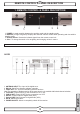
1 3 6 7 4 5 2 8 9
U4150
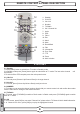
1. POWER: Is used to switch between the working mode and the standby mode.
2. DISPLAY (4-Digit/7-Segment): Displays the received channel number while operating and time while in
standby mode.
3. Remote Sensor: Detects the infrared signals from the remote control unit.
4. CH+/-: To change channels or for navigating and changing values in menus.
REMOTE CONTROL & PANEL DESCRIPTION
1. REMOTE CONTROL & PANEL DESCRIPTION
234
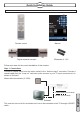
1.2 REAR PANEL DESCRIPTION
1. ANTENNA INPUT:Terr. input of the digital tuner.
2. RS-232: Serial Port allowing software upgrades
3. LOOP OUT: Terr. ouput for cascading to others devices.
Note:The operation of another receiver at the same time is only possible with limited channel selection
4. TV SCART: Output SCART for the connection to a TV set
5. VCR SCART: Output SCART for the connection to a VCR
6. S/PDIF: Coaxial output for digital audio (AC3)
7. Optical S/DIF:Optical output for digital audio (AC3)
8. AC IN: Mains input cable
9. POWER ON/OFF: Allows to completely switch off the receiver