Model 2192 Master Audio Interface Universal Audio Part Number 65-00036 Universal Audio, Inc. Customer Service & Tech Support: 1-877-MY-AUDIO Business, Sales & Marketing: 1-866-UAD-1176 www.uaudio.com FCC Compliance This equipment has been tested and found to comply with the limits for a Class B digital device, pursuant to part 15 of the FCC Rules. These limits are designed to provide reasonable protection against harmful interference in a residential installation.
This equipment generates, uses and can radiate radio frequency energy and, if not installed and used in accordance with the instructions, may cause harmful interference to radio communications. However, there is no guarantee that interference will not occur in a particular installation.
A Letter From Bill Putnam, Jr. __________________________________________________________ Thank you for purchasing the Model 2192 Master Audio Interface, the first product to combine Universal Audio’s long history of high-quality vintage analog gear with advanced digital technology. The 2192 is the perfect two-channel master audio interface for every digital studio.
Important Safety Instructions ___________________________________________________________ Before using this unit, be sure to carefully read the applicable items of these operating instructions and the safety suggestions. Afterwards, keep them handy for future reference. Take special care to follow the warnings indicated on the unit, as well as in the operating instructions. 1. Water and Moisture - Do not use the unit near any source of water or in excessively moist environments. 2.
Table of Contents __________________________________________________________ A Letter From Bill Putnam, Jr. .................................................................................................................. i Important Safety Instructions ................................................................................................................. ii Two Page, Two Minute Guide To Getting Started ......................................................................................
The Two Page, Two Minute Guide To Getting Started __________________________________________________________ No one likes to read owner’s manuals. We know that. We also know that you know what you’re doing—why else would you have bought our product? So we’re going to try to make this as easy on you as possible. Hence this two-page spread, which we estimate will take you approximately two minutes to read.
The Two Page, Two Minute Guide To Getting Started __________________________________________________________ Step 5: In addition to providing a high-quality master clock for your entire studio (or distributing an external clock to your digital equipment), the 2192 can be used for a variety of functions, including analog to digital (A/D) conversion, digital to analog (D/A) conversion, and transcoding (converting between different digital formats).
Front Panel __________________________________________________________ (1) Input Level Meters - This pair of LED level meters indicates the signal strength of the stereo analog inputs relative to the calibrated 0dBFS level. ( see page 31 for more information) (2) Output Level Meters - This pair of LED level meters indicates the signal strength at the stereo analog outputs relative to the calibrated 0dBFS level.
Front Panel __________________________________________________________ Note that the clock source can be independent of the signal used for digital to analog conversion. For example, you could select AES/SPDIF as the clock source but perform D/A conversion on the incoming ADAT optical signal by setting the Analog Outputs DAC Source Select knob ( see #6 on page 7) to ADAT.
Front Panel __________________________________________________________ (4) Sample Rate Select - This six-position knob selects the sample rate used for A/D and D/A conversion. Sample rates of 44.1, 48, 88.2, 96, 176.4, and 192kHz are all supported by the 2192. The 2192 does not perform sample rate conversion! The function of the Sample Rate Select knob varies according to the setting of the Clock knob.
Front Panel __________________________________________________________ source is external, a clock signal must be present at the input selected by the Clock knob. Note: After the Power Switch is turned on, the Clock Status lamp stays off for about 12 seconds while the 2192 power conditioner and analog conversion circuits perform their initial calibrations. The clock must be locked for proper A/D and D/A conversion and for transcoding.
Front Panel __________________________________________________________ (8) Single/Dual switch - The Single/Dual switch specifies whether AES/EBU Single Wire or Dual Wire mode is used. ( see page 28 for more information) When the button is pressed in, AES/EBU Dual Wire mode is used. When the button is out, AES/EBU Single Wire mode is used. Note: This switch has no effect on the SPDIF input. However, the SPDIF output will transmit the same signal as the AES “A” output.
Rear Panel __________________________________________________________ (1) AC Power Connector - Connect a standard, detachable IEC power cable (supplied) here. The third grounding pin is connected to the chassis internally.The 2192’s auto-sensing, multi-stage filtered, universal power supply accepts input power from 100VAC to 240VAC, at 50Hz to 60Hz.
Rear Panel __________________________________________________________ (6) S/PDIF Digital Input - This phono (RCA) connector accepts incoming 24-bit S/PDIF digital audio signals of up to 192kHz from compatible hardware (the copy-protection, pre-emphasis, and consumer/professional bits are ignored). This input can be used for either digital audio with clock or for digital clock only.
Rear Panel __________________________________________________________ (12) ADAT Optical Output - This optical connector transmits digital ADAT optical data to external hardware devices. ( see page 29 for more information) (13) Analog Line Inputs - Analog signals are input to the left and right channels of the 2192 A/D converter via these balanced line-level female XLR connectors. Pin 2 is hot. For unbalanced operation, Pin 3 can be grounded.
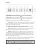
Interconnections __________________________________________________________ Typical Mastering Setup Typical Digital Audio Workstation Setup - 12 -
Interconnections __________________________________________________________ Typical 8-Channel Pro Tools HD Setup - 13 -
Applications: Analog to Digital Conversion __________________________________________________________ Using the 2192 for Analog To Digital Conversion The 2192 enables incoming analog signals to be converted to digital, a process known as analog to digital (A/D) conversion. The resulting digital signal is always in 24-bit format, is sampled at any of six user-selectable rates (44.1, 48, 88.2, 96, 176.4, or 192kHz), and is sent to all rear panel digital outputs (AES, SPDIF, and ADAT optical) simultaneously.
Applications: Analog to Digital Conversion __________________________________________________________ A/D Conversion Using Internal Clock In this configuration, the 2192 is the master system clock. Four word clock outputs are provided so the 2192 can be used as the master system clock without cascading the clock through external devices, which can degrade the clock signal. To perform A/D conversion using the internal clock: 1. Connect the analog source signals to the 2192 rear panel analog line inputs. 2.
Applications: Analog to Digital Conversion __________________________________________________________ A/D Conversion Using External Clock In this configuration, the 2192 is synchronized (slaved) to an external master digital source clock. Two separate word clock inputs, as well as AES/EBU, S/PDIF, and ADAT optical, can be used as clock sources for external synchronization.
Applications: Digital to Analog Conversion __________________________________________________________ Using the 2192 for Digital To Analog Conversion The 2192 enables incoming digital signals (arriving via its rear panel AES, SPDIF, or ADAT optical inputs) to be converted to analog, a process known as digital to analog (D/A) conversion. All 24 bits of the digital input signal are converted, at sampling rates of 44.1, 48, 88.2, 96, 176.4, or 192kHz.
Applications: Digital to Analog Conversion __________________________________________________________ D/A Conversion Using Digital Audio Source Clock In this configuration, the 2192 is synchronized to the clock signal that is embedded within the digital audio signal that is being converted to analog. To perform D/A conversion using the digital audio source clock: 1. Connect the 2192 rear panel analog line outputs to the analog inputs of the destination device (patch bay, mixer, DAW, etc). 2.
Applications: Digital to Analog Conversion __________________________________________________________ D/A Conversion Using External Word Clock In this configuration, D/A conversion is accomplished while the 2192 is synchronized to one of its two independent Word Clock inputs. To perform D/A conversion while synchronized to word clock: 1. Connect the 2192 rear panel analog line outputs to the analog inputs of the destination device (patch bay, mixer, DAW, etc). 2.
Applications: Digital to Analog Conversion __________________________________________________________ D/A Conversion of AES/SPDIF Audio Using ADAT Clock In this configuration, an incoming AES or SPDIF digital audio signal is converted to analog while the 2192 is synchronized to the clock arriving at the ADAT input. (The audio portion [if any] of the ADAT signal is ignored.) To perform AES or SPDIF D/A while synchronized to ADAT clock: 1.
Applications: Digital to Analog Conversion __________________________________________________________ D/A Conversion of ADAT Audio Using AES/SPDIF Clock In this configuration, an incoming ADAT digital audio signal is converted to analog while the 2192 is synchronized to the clock of an AES or SPDIF signal. (The audio portion [if any] of the external AES or SPDIF signal is ignored.) To perform ADAT D/A while synchronized to AES or SPDIF clock: 1.
Applications: Transcoding __________________________________________________________ Using the 2192 for Transcoding (Converting Digital Formats) The 2192 can transcode (convert) digital audio data between AES/EBU, S/PDIF, and ADAT optical formats in real time. The transcoded digital audio input signal is output to all 2192 digital audio outputs simultaneously. Transcoding can be performed using any of the available clock sources.
Applications: Transcoding __________________________________________________________ Transcoding Using Digital Audio Source Clock In this configuration, the 2192 is synchronized to the clock signal that is embedded within the digital audio source signal that is being transcoded. To perform transcoding using the digital audio source clock: 1. Using the appropriate digital cable, connect the digital output from the external digital audio source device to the desired 2192 digital input. 2.
Applications: Transcoding __________________________________________________________ Transcoding Using Alternate Clock In this configuration, the 2192 is synchronized to an external clock master. The digital audio source device can be synchronized to the same clock, or to the 2192. To perform transcoding while using an alternate source clock: 1. Using the appropriate digital cable, connect the digital output from the external digital audio source device to the desired 2192 digital input. 2.
The Technical Stuff __________________________________________________________ History of the Model 2192 In 2000, legendary audio engineer Bill Putnam Sr. was awarded a Technical Grammy for his multiple contributions to the recording industry. Highly regarded as a recording engineer, studio designer/operator and inventor, Putnam was considered a favorite of musical icons Frank Sinatra, Nat King Cole, Ray Charles, Duke Ellington, Ella Fitzgerald and many, many more.
The Technical Stuff __________________________________________________________ Digital Clocking Primer Digital clocking is a complicated issue, with a number of important aspects that are often not very well understood. First and foremost, a digital clock is used to maintain synchronization between different digital devices. There are two primary purposes for clock synchronization: 1. Digital Conversion.
The Technical Stuff __________________________________________________________ • Clock jitter in digital transmission can be caused by a bad source clock, inferior cabling or improper cable termination, and/or signal-induced noise (called “pattern-jitter” or “symboljitter.”) Digital signal formats like AES/EBU, S/PDIF, and ADAT all embed a clock in the digital signal so the receiving device can synchronize to the transmitted data bits correctly.
The Technical Stuff __________________________________________________________ Model 2192 Overview The 2192 Master Audio Interface is kind of like the Swiss Army knife of digital audio. It provides two channels of analog to digital (A/D) conversion, two channels of digital to analog (D/A) conversion, a format transcoder, and a word clock generator/distribution amplifier... all in one box.
The Technical Stuff __________________________________________________________ SPDIF Digital I/O The 2192 accepts incoming 24-bit S/PDIF digital audio signals up to 192kHz from compatible hardware. The copy-protection, pre-emphasis, and consumer/professional bits are ignored. The SPDIF input can be used for either digital audio with clock or for digital clock only.
The Technical Stuff __________________________________________________________ Subclocking/Overclocking Subclocking occurs if the 2192 is synchronized to an external clock that is running at 2x or 4x the 2192’s sample rate. Overclocking occurs if the 2192 is synchronized to an external clock that is running at 1/2 or 1/4 of the 2192’s sample rate.
The Technical Stuff __________________________________________________________ Metering Level metering for each of the stereo input and output channels is provided by its own front-panel 10-segment LED display. ( see #1 and #2 on page 4) Each channel has timed peak/hold digital clip/maximum output indicators. All LED segments except CLIP are driven by the analog metering circuitry (the meters are tied to the converters, not the analog trims). The red CLIP indicators are driven by the digital circuitry.
The Technical Stuff __________________________________________________________ Model 2192 Circuitry The 2192 Master Audio Interface was designed with two primary goals: the highest-quality audio fidelity and ease of use. Specifications can be useful but are sometimes misleading because they don’t always tell the whole story. Something can look great on paper, but still sound bland.
The Technical Stuff __________________________________________________________ errors caused by transients, overshoot, intermodulation distortion, etc. are big and must be corrected for by huge amounts of negative feedback. However, the intermediate circuit elements within the op-amp don’t get corrected immediately because these devices don’t have the required infinite frequency response assumed by the classical circuit models.
The Technical Stuff __________________________________________________________ bias points and signal levels of our all discrete, Class-A op-amp analog circuitry to provide the perfect transition from pristine nominal levels to hard-driven high levels so the 2192 still produces musical results before digital clipping occurs. Leaving the signal pristine until harsh clipping occurs introduces aliasing and isn’t the way audio gear is supposed to work.
The Technical Stuff __________________________________________________________ Maintenance Information Line Trim Procedure To calibrate the analog inputs, a digital signal meter and an accurate analog reference generator with low impedance outputs are required. To calibrate the analog outputs, a digital signal generator and an accurate analog dB level meter with balanced inputs are required.
The Technical Stuff __________________________________________________________ Output Level Meters Calibration Having completed the output trim procedure as described on the previous page, the output meters will need to be recalibrated. (Note that the input trims have no effect on the meters, so no calibration is needed after input trims are adjusted.) The factory default has the unit set so that a 0dBFS digital level equals an analog level of +22dB.
The Technical Stuff __________________________________________________________ Figure 4: Output Level Meter Calibration Trimpots Important: Do not adjust the Offset trimpots! These settings are optimized at the factory.
The Technical Stuff __________________________________________________________ Ground Isolation Jumpers Changes to internal jumpers should only be made by qualified personnel. Be sure to disconnect AC power before opening the unit! Each of the eight balanced connectors (the analog and AES digital I/O) can individually isolate pin 1 from ground if desired via an internal jumper block. The table below indicates which internal jumper is used for each balanced connector.
The Technical Stuff __________________________________________________________ Block Diagram - 39 -
The Technical Stuff __________________________________________________________ Dynamic Range: A/D Dynamic Range: D/A - 40 -
The Technical Stuff __________________________________________________________ Frequency Response - 41 -
Glossary of Terms __________________________________________________________ A/D - An acronym for “Analog to Digital,” referring to the conversion of analog signal to digital. ADAT - An acronym for “Alesis Digital Audio Tape.” ADAT was the name given to the Alesis-branded products of the 1990s which recorded eight tracks of digital audio on a standard S-VHS video cassette.
Glossary of Terms _______________________________________________________________________ D/A - An acronym for “Digital to Analog,” referring to the conversion of digital signal to analog. DAW - An acronym for “Digital Audio Workstation”—that is, any device that can record, play back, edit, and process digital audio. dB - Short for “decibel,” a logarithmic unit of measure used to determine, among other things, power ratios, voltage gain, and sound pressure levels.
Glossary of Terms __________________________________________________________ Internal clock - A clock signal derived from onboard circuitry. (see “Clock”) I/O - Short for “input/output.” kHz - Short for “kiloHertz” (a thousand Hertz), a unit of measurement describing a thousand analog audio cycles (or digital samples) per second.
Glossary of Terms __________________________________________________________ Sample rate conversion - The process of altering a digital signal’s sample rate to a different sample rate. The 2192 does not perform sample rate conversion. Single Wire - (sometimes referred to as “Double Fast”) The newest revised format of AES/EBU data transfer that accommodates sample rates of 176.4kHz or 192kHz.
Recall Sheet _______________________________________________________________________ - 46 -
Specifications _______________________________________________________________________ Analog: Inputs Connectors Type Common-mode rejection ratio (CMRR) Impedance Maximum input level 2x balanced XLR female connectors DC coupled, dual-differential >90dB ~1.5k ohms +31dBu Outputs Connectors Type Impedance Maximum output level 2x balanced XLR male connectors DC coupled, dual-differential ~95ohms +23dBu Frequency Response (analog input to ADC to DAC to analog output, referenced to 1kHz, Fs = 192kHz) +/- 0.
Specifications __________________________________________________________ Digital: 2-Channel S/PDIF Connectors Type Dual stacked RCA Unbalanced, transformer driven output, AC coupled input 2-Channel AES/EBU Connectors Transformer isolated, balanced XLR (x4) Single wire and dual-wire modes (for sample rates of 176.
Specifications _______________________________________________________________________ Dynamic range (measured using -38dBu = -60dBFS input at 1kHz) Frequency response (relative to 1kHz) Phase response Residual noise (200Hz-20kHz) Total Harmonic Distortion + Noise (measured at 1kHz) 118dB (A-weighted), 115dB (unweighted) (see page 38) +/- 0.02dB, 10Hz to 20kHz @ Fs=44.1kHz +/- 0.04dB, 10Hz to 40kHz @ Fs=96kHz <0.1°, 10Hz to 1kHz, -1.
(This page intentionally left blank)
Additional Resources/Product Registration/Warranty/Service & Support __________________________________________________________ Additional Resources We’ve got a pretty cool website, if we may say so ourselves. Check us out at http://www.uaudio.com.