
Manual

Front Panel
_____________________________________________________________
5
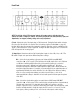
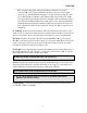
(8) High Boost/Cut - Selects the amount of cut or boost applied by the high shelving filter. The
positive and negative numbers on the front panel denote dB values (-9, -6, -4.5, -3, -1.5, 0, +1.5, +3,
+4.5, +6, +9).
(9) Low Frequency - Selects the corner frequency for the low shelving filter. Available frequencies are
70 Hz, 100 Hz, and 200 Hz.
(10) Low Boost/Cut - Selects the amount of cut or boost applied by the low shelving filter. The
positive and negative numbers on the front panel denote dB values (-9, -6, -4.5, -3, -1.5, 0, +1.5, +3,
+4.5, +6, +9.
(11) +48 V - Most modern condenser microphones require +48 volts of phantom power to operate.
This toggle switch applies 48 volts to the 6176 MIC INPUT when the switch is up (in the +48V
position). ( See page 26 for more information about phantom power)
(12) Power - Turns the 6176 power on or off. When powered on, the purple LED immediately above this
switch is lit.
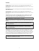
(13) Join / Split - This switch allows separate use of the preamp section and the limiter / compressor
section. When the switch is in the SPLIT (down) position, each side of the 6176 acts as a separate
device, each with its own separate rear panel in / out connections. ( see #1 and #2 on page 9 and
#5 and #6 on page 9) When the switch is in the JOIN (up) position, the 6176 behaves like a channel
strip, with the preamp output automatically routed internally to the limiter / compressor section.
Keep phantom power off (switch down) when it is not required.
To avoid loud transients, always make sure phantom power is off when connecting or
disconnecting microphones.
Always check the power requirements of your microphone with the manufacturer before
applying phantom power.
When operating in JOIN mode, the rear panel Preamp LINE OUT and the Limiter/Compressor
LINE IN jacks are automatically disconnected.