
User Manual


Apollo 8 Hardware Manual Interconnections 29
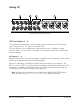
Basic Setup
This diagram illustrates a simple Apollo 8 setup that could be used by an individual
musician/engineer for recording and mixing. It shows an electric guitar connected to the
Hi-Z input of channel 1 and a microphone connected to the XLR input of channel 2 so
they can both be recorded simultaneously.
Key points for this example:
• Two preamp channels are used (electric guitar and microphone)
• Mic/Line switch for channel 2 is set to MIC
• Monitor outputs are connected to powered monitors (or an amp+speaker system)
Basic Apollo 8 connections
MONITOR
PREAMP
21
POWER
HEADPHONES
PAD
INPUT
+48V
Ø LINK
METER
ALT
FCN
OUT
HI-Z 1 HI-Z 2
OFF
1 2
C
0
-6
-3
-9
-12
-15
-18
-21
-27
88.2
RATE
44.1
48
176.4
96
192
HOST
CLOCK
INT
EXT
METER
IN
OUT
1 2 3 4 5 6 7 8
CLIP
0
-6
-3
-9
-12
-15
-18
-21
-27
LINE
Hi-Z
1 2
C
0
-6
-3
-9
-12
-15
-18
-21
-27
88.2
RATE
44.1
48
176.4
96
192
HOST
CLOCK
INT
EXT
METER
IN
OUT
1 2 3 4 5 6 7 8
CLIP
0
-6
-3
-9
-12
-15
-18
-21
-27
MIC
Hi-Z
INPUT
1
WORD
CLOCK
4 2
MIC/LINE IN
3 1
LINE IN
7 5
ADAT S/MUX
75 Ω
TERM
68R
L1357
248 6
WORD CLOCK
S/PDIF
Mic
Thunderbolt
Computer
Headphones
Monitor Speakers
Instrument