
User Manual


Apollo 8 Hardware Manual Interconnections 30
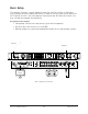
Typical Setup
This diagram illustrates an Apollo 8 setup that could be used to record two musicians
simultaneously. In this setup, only analog devices are connected; digital I/O is not used.
The example shows an electric guitar and electric bass connected to the Hi-Z inputs.
Microphones are connected to XLR inputs of channel 3 and 4, and a stereo keyboard is
connected to line inputs 5 and 6. Both headphone outputs are used during tracking and
the left/right monitor outputs are connected to a loudspeaker system for mixdown.
Key points for this example:
• Mic/Line switches for channels 3 and 4 are set to MIC
• Unique mixes can be crafted via Console’s CUE sends and routed to each
headphone output for “more me” during tracking
Typical Apollo 8 connections
MONITOR
PREAMP
21
POWER
HEADPHONES
PAD
INPUT
+48V
Ø LINK
METER
ALT
FCN
OUT
HI-Z 1 HI-Z 2
OFF
1 2
C
0
-6
-3
-9
-12
-15
-18
-21
-27
88.2
RATE
44.1
48
176.4
96
192
HOST
CLOCK
INT
EXT
METER
IN
OUT
1 2 3 4 5 6 7 8
CLIP
0
-6
-3
-9
-12
-15
-18
-21
-27
LINE
Hi-Z
1 2
C
0
-6
-3
-9
-12
-15
-18
-21
-27
88.2
RATE
44.1
48
176.4
96
192
HOST
CLOCK
INT
EXT
METER
IN
OUT
1 2 3 4 5 6 7 8
CLIP
0
-6
-3
-9
-12
-15
-18
-21
-27
MIC
Hi-Z
INPUT
1
WORD
CLOCK
4 2
MIC/LINE IN
3 1
LINE IN
7 5
ADAT S/MUX
75 Ω
TERM
68R
L1357
248 6
WORD CLOCK
S/PDIF
Headphones 2
Instrument 1
Instrument 2
Headphones 1Stereo
Keyboard
Thunderbolt
Computer
Monitor Speakers
MicMic