
User Manual


Apollo Twin MkII Hardware Manual Controls & Connectors 26
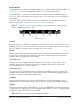
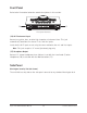
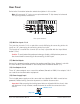
Rear Panel
Refer to the illustration below for control descriptions in this section.
Note: All rear panel ¼” jacks can accept unbalanced TS (tip-sleeve) or balanced
TRS (tip-ring-sleeve) connections.
Rear panel elements
(16) Mic/Line Inputs 1 & 2
The jacks for channels 1 & 2 accept either a male XLR plug for connecting to the mic
input, or a ¼” phone plug for connecting to the line input.
The input that is used for the channel (mic or line) is specified with the Input Select
button (13-a).
Caution: To avoid potential equipment damage, disable +48V phantom power on
the channel before connecting or disconnecting its XLR input.
(17) Monitor Outputs
Connect the powered monitor speakers (or speaker amplifiers) here. Volume is set with
the Level knob (1) when Monitor is selected (8) with the Monitor button (11).
(18) Line Outputs 3 & 4
These ¼” phone outputs are accessed via software (Console or DAW). Line outputs 3 & 4
are used to send audio to other equipment.
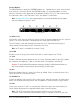
(19) Power Supply Input
The included power supply must be connected here (Apollo Twin MkII cannot be bus
powered). Rotate locking connector to prevent accidental disconnection.
Important: After ensuring the locking barrel tabs are aligned with the chassis slots
and the barrel is fully inserted, rotate the barrel to secure the connector to the
chassis.
MIC/LINE 1
MIC/LINE 2
3 L
4 R
LINE OUT MONITOR
OPTICAL IN
OFF ON
12VDC
POWER
171819
22
21
20
16
12VDC
1. Align Tabs
2. Rotate to Lock