Thunderbolt 3 Audio Interface Apollo x16 Hardware Manual Manual Version 080828 www.uaudio.
A Letter from Bill Putnam Jr. Thank you for choosing this Apollo X Series audio interface to become a part of your studio. We know that any new piece of gear requires an investment of time and money — and our goal is to make your investment pay off. Universal Audio interfaces like Apollo X exemplify a commitment to craftsmanship that we’ve forged over the past 60 years — from our original founding in the 1950s by my father, Bill Putnam Sr.
Table Of Contents Tip: Click any section or page number to jump directly to that page. A Letter from Bill Putnam Jr................................................................... 2 Introduction.......................................................................................... 4 Apollo x16 Features............................................................................................ 6 Apollo x16 Documentation Overview.....................................................................
Introduction 16 Channels of Elite Audio Conversion, HEXA Core Processing and Surround Sound Monitoring. The flagship Apollo x16 allows music producers, project, and post-production studios to track, overdub, and mix with new world-beating A/D and D/A conversion, HEXA Core UAD plug-in processing, and 7.1 surround sound monitoring† — all in a sleek rackmount Thunderbolt 3 audio interface for Mac or PC.
Realtime UAD HEXA Core Processing Apollo x16 features new HEXA Core processing, with six DSP chips and 50% more UAD plug-in processing power than previous Apollos. This lets you run more UAD plug-ins, whether you’re tracking in real time with channel strips from Neve, Manley, Helios, or API, or running high UAD plug-in counts when mixing in your DAW.
Apollo x16 Features Key Features: • • • • • • • • • • 18 x 20 Thunderbolt 3 audio interface with class-leading 24-bit/192 KHz conversion HEXA Core Realtime UAD Processing for tracking through UAD plug-ins at nearzero latency, regardless of audio buffer size Surround monitor controller up to 7.
Monitoring • • • • Independently-addressable stereo monitor outputs (in addition to 16 line outputs) Front panel control of monitor levels and muting Front panel pre-fader metering of monitor bus levels Digital AES/EBU outputs can mirror the analog monitor outputs UAD-2 HEXA Inside • • • • • Six SHARC® DSP processors Realtime UAD Processing on all of Apollo x16’s analog and AES/EBU inputs Same features and functionality as other UAD-2 products when used with DAW Can be combined with other UAD-2 devices f
Apollo x16 Documentation Overview Documentation for Apollo x16 and UAD Powered Plug-Ins are separated by areas of functionality, as described below. The user manuals are placed on the system drive during software installation, and they can be downloaded at help.uaudio.com. Note: All manual files are in PDF format. PDF files require a free PDF reader application such as Acrobat Reader (Mac & Windows) or Preview (Mac). Apollo Hardware Manuals Each Apollo model has a unique hardware manual.
Accessing Installed Documentation Any of these methods can be used to access installed documentation: • • • Choose “Documentation” from the Help menu within the Console application Click the “Product Manuals” button in the Help panel within the UAD Meter & Control Panel application Manuals are also available online at help.uaudio.com Host DAW Documentation Each host DAW software application has its own particular methods for configuring and using audio interfaces and plug-ins.
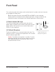
Front Panel This section describes the features and functionality of all controls and visual elements on the Apollo x16 front panel. Tip: All front panel functions except METER and POWER can be controlled remotely with the included Console software application. Changes made with the front panel controls are mirrored in the Console application, and vice versa.
L AUDIO, INC. 16 4 3 5 7 8 9 10 METER 9 10 11 12 13 14 15 16 12 13 MONITOR MONITOR ALT FCN 11 6 Main Apollo x16 front panel elements (3) Channel Level Meters 17 75 Ω TERM The 10-segment LED channel meters display the input or output signal peak levels for analog channels 1 – 16. Input or output metering is selected with the METER switch (#9),18and the input/output state is shown by the METER indicators (#6).
(5) CLOCK Indicators The clock source and status are displayed with these indicators. Either internal (INT) or external (EXT) is displayed. The clock source is set within the Console application; see the Apollo Software Manual for details. Internal Clock When set to internal clock, the INT indicator is illuminated white. External Clock Apollo x16 can use an external digital clock source from the Word Clock or AES/EBU inputs.
(8) Monitor Output Level Meters The 10-segment LED meters display the signal peak output levels of the rear panel Left & Right Monitor outputs at the output of the D/A converters. These meters are before the Monitor Level control (pre-fader) and reflect the D/A converter levels regardless of the current Monitor Level and Headphone Level knob settings. The dB values of the monitor meter LEDs are indicated between the left and right channel meters.
(11) Monitor Function Switch (FCN) This is an assignable switch that can be configured to control one of three monitoring functions. The function of the switch is configured with the FCN SWITCH ASSIGN menu in the Hardware panel within the Console Settings window. Refer to the Apollo Software Manual for details. The amber LED within the switch flashes when the monitoring function is active. The function is toggled with the switch is pressed again.
(13) Monitor Level & Monitor State Indicator Tip: The Monitor Level and Monitor State indications are reflected in the Monitor column within the Console application. Monitor Output Level Indicator The relative signal level at the rear panel monitor outputs (and ALT monitor outputs, if configured) is indicated by the illuminated ring surrounding the Monitor Level knob. This indicator is after the Monitor Level control (post fader).
6 Rear Panel 15 17 POWER IN 75 Ω TERM 18 19 20 MONITOR OUTPUT AES/EBU OUT UNIVERSAL AUDIO, INC. IN WORD CLOCK +12VDC 9.0A 16 Apollo x16 rear panel (digital portion) (15) Power Input The included external power supply connects to this 4-pin locking XLR jack. Apollo x16 requires 12 volts DC power and draws a maximum of 72 watts (30 watts typical). To eliminate risk of circuit damage, connect only the factory-supplied power supply.
Digital I/O (17) 75 Ohm Word Clock Termination Switch This switch provides internal 75-ohm word clock input signal termination when required. Word clock termination is active when the switch is engaged (depressed). Apollo x16’s termination switch should only be engaged when Apollo x16 is set to sync to external word clock and it is the last device at the receiving end of a word clock cable.
(19) AES/EBU Ports The AES/EBU ports provide two channels of digital I/O with resolutions up to 24-bit at 192 kHz via XLR connectors. For optimum results, use only high-quality 110-ohm XLR cables specifically designed for AES/EBU digital audio. SR Convert Sample rate conversion can be enabled on the AES/EBU input. This function is set in the AES/EBU input channel strip within the Console application.
Analog I/O 19 20 MONITOR OUTPUT AES/EBU OUT IN 2 21 22 LINE OUT 9-16 LINE IN 9-16 LINE OUT 1-8 LINE IN 1-8 1 Apollo x16 rear panel (analog portion) (20) Left & Right Monitor Outputs These balanced XLR jacks are line-level analog outputs typically used for connection to a stereo loudspeaker monitoring system. The signal levels at these outputs are controlled with the Monitor Level & Mute knob (#12). The Monitor Outputs are DC coupled.
(21) Line Outputs 1 – 16 The 16 analog outputs are accessed via dual female DB25 connectors. Each DB25 jack carries eight balanced line-level channel outputs using standardized Tascam wiring. The Line Outputs are DC coupled. Note: See DB25 Wiring for connector pinouts. Line Output Headroom By default, the operating level of the line outputs is +20 dBu.
(22) Line Inputs 1 – 16 The 16 analog inputs are accessed via dual female DB25 connectors. Each DB25 jack carries eight balanced line-level channel inputs using standardized Tascam pinouts. The Line Inputs are DC coupled. Note: See DB25 Wiring for connector pinouts. Line Input Headroom By default, the operating level of the line inputs is +20 dBu.
Interconnections Installation Notes • • • Apollo X may get hot during normal operation if it doesn’t receive adequate airflow circulation around its chassis vents. For optimum results when mounting Apollo X in a rack, leaving at least one empty rack space above the unit to allow adequate airflow for cooling is strongly recommended. If Apollo X is installed near other heat generating equipment, external cooling (such as a fan) may be needed to keep the ambient temperature below 104ºF (40ºC).
About Thunderbolt 3 Ports and Cables Important: Although Thunderbolt 3 always uses USB-C connectors, not all USB-C ports are Thunderbolt 3 ports. Similarly, not all USB-C cables are Thunderbolt 3 cables. Always connect Apollo x16 to a Thunderbolt 3 port with a Thunderbolt 3 cable. USB-C is not Thunderbolt 3 Thunderbolt 3 uses USB-C connections to transfer data and power. However, USB-C is simply a connector type; it doesn’t determine the type of data used by the connector.
Typical Setup This diagram illustrates an Apollo x16 example system. Key points for this example: • • • • Either Thunderbolt 3 port can be used for the host computer connection The Monitor outputs are connected to powered monitors (or an amp+speaker system) DB25 audio snakes are used for connections to line-level audio gear Although this example uses XLR connectors, DB25 snakes that terminate to XLR, TRS, or other DB25 connectors can be used Monitor Speakers POWER IN OUT UNIVERSAL AUDIO, INC.
Apollo Expanded: Multi-Unit Thunderbolt 3 Wiring The diagram below illustrates an example of how to interconnect multiple Apollo units and the host computer via Thunderbolt 3. Important: For complete details about system operation when multi-unit cascading, see the Apollo Software Manual. Thunderbolt 3 Computer UAD-2 Satellite Thunderbolt TB3 to TB2 Adapter POWER IN Expander Unit OUT UNIVERSAL AUDIO, INC.
Software Setup Note: Items on this page are detailed in the Apollo Software Manual. System Requirements All system requirements must be met for Apollo X to operate properly. Before proceeding with installation, see the system requirements in the Apollo Software Manual. Software Installation The software must be installed to use the hardware and UAD plug-ins. The UAD Powered Plug-Ins software installer contains the Apollo X software, drivers, and UAD plug-ins.
Specifications All specifications are typical performance unless otherwise noted. Tested with the Audio Precision APx555 Audio Analyzer under the following conditions: 48 kHz internal sample rate, 24-bit sample depth, 20 kHz measurement bandwidth, +24 dBu headroom, balanced output, and internal clock.
ANALOG I/O Line Inputs 1 – 16 Frequency Response 20 Hz – 20 kHz, ±0.05 dB Dynamic Range 124 dB (A–weighted) Total Harmonic Distortion + Noise Ratio (1 kHz @ 23 dBu) -115 dB (0.000180%) Maximum Input Level (Reference Level @ +4 dBu) 24 dBu, Balanced Maximum Input Level (Reference Level @ -10 dBV) Input Impedance 6.2 dBV (8.4 dBu), Balanced Connector Type 10k Ohms Two Female DB25, Tascam wiring Line Outputs 1 – 16 Frequency Response 20 Hz – 20 kHz, ±0.
ELECTRICAL Power Supply External AC-to-DC Power Supply, Level VI compliant AC Input Connector Type IEC Male AC Requirements 100V – 240V AC, 50 – 60 Hz DC Connector Type XLR 4-Pin Locking Male (Neutrik P/N NC4MDM3-H) DC Requirements 12 VDC, 6A Maximum Power Consumption 72W (30W typical) ENVIRONMENTAL Ambient Temperature Range 32º to 104º F (0º to 40º C) MECHANICAL Dimensions Width 19 in (48,26 cm) Height (1U rack space) 1.75 in (4,45 cm) Depth, Chassis Only 12.
Apollo x16 Hardware Manual DB25 FEMALE DB25 FEMALE PAD +4 dBu / -10 dBV SELECT A/D Global Setting +4dB 30 75 Ω BNC BNC TB TB THUNDERBOLTTM 3 OPTION CARD PCIe OPTION CARD SLOT SYSTEM CONTROL CLOCKING / SYNC MIXER XLR MALE WORD CLOCK I/O THUNDERBOLTTM 3 PORTS WC TERM ON/OFF INTERNAL TALKBACK MIC ø +20dBu / +24dBu LOW-CUT POLARITY HEADROOM SELECT ON/OFF CONTROL Apollo x16 Hardware Block Diagram V02 9 - 16 1-8 LINE INPUTS 1 - 16 AES/EBU OUT AES/EBU IN XLR FEMALE ARM® PROCESSOR 6 SHAR
DB25 Wiring Apollo x16’s analog I/O is accessed via 25-pin D-sub female connectors. Each DB25 jack carries eight balanced line-level audio channels on the standardized Tascam pinouts also used with Digidesign and Avid products. DB25 Connector Pin Numbers The pin numbers for female DB25 connectors are shown in the diagram below. When facing the Apollo x16 rear panel, pin 1 is the upper rightmost pin.
Troubleshooting If Apollo x16 isn’t behaving as expected, here are some common troubleshooting items to confirm. If you are still experiencing issues after performing these checks, contact Technical Support.
Notices Warranty Universal Audio provides a limited warranty on all UA hardware products. To learn more, visit help.uaudio.com. The limited warranty gives you specific legal rights. You may also have other rights which vary by state or country. Repair Service If you are having trouble with Apollo X, first check all system setups, connections, and operating instructions. If that doesn’t help, contact our technical support team. To learn about repair service, or for technical support, visit help.uaudio.com.
Important Safety Information Before using this unit, be sure to carefully read the applicable items of these operating instructions and the safety suggestions. Afterwards, keep them handy for future reference. Take special care to follow the warnings indicated on the unit, as well as in the operating instructions. 1) Read these instructions. 2) Keep these instructions. 3) Heed all warnings. 4) Follow all instructions. 5) Do not use this apparatus near water. 6) Clean only with dry cloth.
FCC Compliance Federal Communications Commission United States Class A Manual Statements Note: This equipment has been tested and found to comply with the limits for a Class A digital device pursuant to Part 15 of the FCC Rules. These limits are designed to provide reasonable protection against harmful interference when the equipment is operated in a commercial environment.
Disclaimer The information contained in this manual is subject to change without notice. Universal Audio, Inc. makes no warranties of any kind with regard to this manual, including, but not limited to, the implied warranties of merchantability and fitness for a particular purpose. Universal Audio, Inc. shall not be liable for errors contained herein or direct, indirect, special, incidental, or consequential damages in connection with the furnishing, performance, or use of this material.
Technical Support Universal Audio Knowledge Base The UA Knowledge Base is your complete technical resource for configuring, operating, troubleshooting, and repairing UA products. You can watch helpful support videos, search the Knowledge Base for answers, get updated technical information that may not be available elsewhere, and more. UA Knowledge Base YouTube Support Channel The Universal Audio Support Channel at youtube.com includes helpful support videos for setting up and using UA products.
www.uaudio.