
Instruction Manual


3
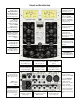
Preamp Operation Instructions (Channel A & Channel B)
DI Switches the Preamp source to the DI inputs for use with electric guitars, basses, other electrified
instruments or line-level signals from keyboards or effects processors. Turning on the DI switch
will turn off the +48V switch.
[see APPLICATION NOTES: Preamps & Connecting balanced line levels to DI inputs]
+48 Switches "phantom power" to the Mic Input XLR jacks. Mic power is slowly ramped on and off, as
indicated by the digital display to prevent loud audio transients. Turning on the +48V switch will turn off
the DI switch.
GAIN Controls the Preamp GAIN through 60 steps of 1dB when the Mic input is selected and 43 steps of 1dB
when the DI input is selected. While turning the knob, the digital display shows the amount of GAIN
applied between the Preamp input and output jacks. Mic GAIN range is +10dB to +69dB for the highest
GAIN Trim
setting (+24 dBu) and -14 to +45dB for the lowest GAIN Trim
setting (0 dBu). DI GAIN range is
0 to +42dB for the highest GAIN Trim
setting, and -24 to +18 for the lowest GAIN Trim
setting.
Note: When listening closely, it may be possible to hear low-level audio switching as the Preamp steps
through its 1dB GAIN settings. Therefore it is not advisable to adjust GAIN settings while recording.
dB (& Lock) Switches on the digital display to show the Preamp GAIN continuously. Holding the dB switch for 2
seconds turns on or off the red Lock LED. The Lock function prevents accidental alteration of GAIN and 6
Preamp switches during live recordings or performances.
Phase Inverts the Phase (polarity) of the Preamp channel (Mic or DI). When MS-STEREO is activated, inverting
the phase of either Channel A or Channel B Preamp causes the left-right stereo image to be reversed.
[see APPLICATION NOTES: Phase Inversion & MS-STEREO]
LO CUT Switches the LO CUT filter on or off at 3 frequencies: 30Hz, 70Hz, or by pressing both simultaneously for
100Hz. Audio response is -3dB at the selected filter frequency with -18dB per octave roll off. For
example, the 100Hz filter attenuates 100Hz by 3 dB, 50Hz by 21dB and 25Hz by 39dB. The filters are
uniquely designed to prevent low-frequencies from overloading the Preamp before filtering occurs.
[see APPLICATION NOTES: LO CUT Filtering]
GAIN Trim Controls the GAIN Trim setting for the Preamp Channels on the digital display. The -/+ keys blink, while
the red PEAK LED's light to prompt calibration of the maximum audio level sent from the Pre Output jacks
before clipping occurs (dBu sine wave). GAIN Trim
is controlled in 1dB steps from 0dBu to +24dBu. The
displayed dBu value should be set to match the "maximum input level" on the recording interface. GAIN
Trim
does not affect Preamp audio levels sent to the Cue Mixer or to the A/B Stereo output. The GAIN
Trim
switch will turn itself off 1 minute after it is no longer being adjusted.
The Preamp is designed to optimize signal-to-noise ratio and headroom relative to the GAIN Trim
level. If
set correctly, the maximum output level of the Preamp will match the maximum input level of the
downstream workstation, recorder, or mixer. This frees up the user to set and maintain levels in Remote
Preamp Controller locations where it is difficult or impossible to read meters or clip LEDs on the
downstream device.
[see APPLICATION NOTES: Matching Pre Outputs to DAW Inputs, which provides max input levels of many
popular interfaces]
PEAK LEDs The red PEAK LED indicates that the Preamp has reached or exceeded preamp's maximum output level
set by the GAIN Trim control. The yellow PEAK LED indicates a warning that the Preamp signal is
approaching the GAIN Trim max dBu level. The Preamp signal does not clip or distort when only a yellow
warn LED is lit. Hold the GAIN Trim
switch 1 second to set the PEAK warn LED’s threshold. This level is
adjustable from 0 to -12 dB below the GAIN Trim max dBu level in 1dB steps.