
Instruction Manual
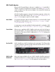


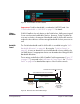
Table Of Contents
- UAD System Manual
- Table Of Contents
- Introduction
- UAD Installation
- UAD System Overview
- My.uaudio.com
- Using Multiple UAD Devices
- UAD Meter & Control Panel
- Using UAD Powered Plug-Ins
- Tempo Sync
- UAD Delay Compensation
- UAD-2 SOLO/Laptop
- UAD-2 Satellite
- History
- Index
UAD System Manual - 109 - Chapter 11: UAD-2 Satellite
It is possible to configure a FireWire bus to run at both FW400 and FW800
speeds simultaneously if the host computer bus is FW800, supporting maxi-
mum throughput for a mix of FW400+FW800 devices. This is accomplished
by putting any/all FW400 devices AFTER any/all FW800 devices in a daisy
chain (see Figure 34 on page 109).
Daisy-chain FireWire 400 devices AFTER the FireWire 800 devices in a FW800 bus
If (and only if) FireWire 400 devices are attached to a FireWire 800 bus after
the end of all FireWire 800 devices in a daisy-chain (Figure 34), the FireWire
800 devices will operate at 800 megabits while the FireWire 400 device op-
erates at 400 megabits.
Important: This is the recommended configuration when UAD-2 Satellite is
sharing a FireWire 800 bus with FireWire 400 devices.
FireWire Bandwidth
All devices on a FireWire bus must share the available data bandwidth of the
bus, including hard drives and audio interfaces as well as UAD-2 Satellite. If
there is not enough FireWire bandwidth to handle all the data traffic on the
bus, performance issues (such as audio clicks/pops/dropouts or UAD over-
loads) could occur.
Bandwidth
Guage
When UAD-2 Satellite is connected, the UAD Meter window displays the
FireWire Bandwidth gauge (Figure 35 on page 110), showing the amount of
FireWire bandwidth being used by UAD-2 Satellite and other FireWire de-
vices on the bus. Figure 36 on page 110 details all of the elements in the
gauge.
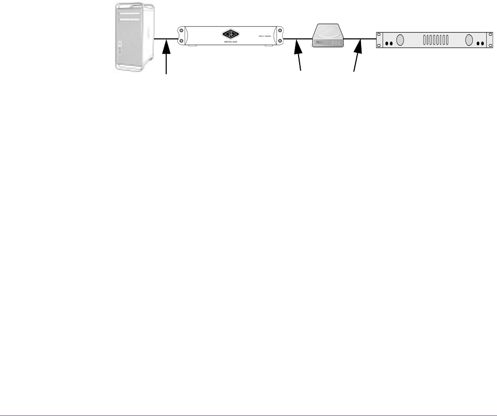
Figure 34. FireWire 800 bus – devices running at 800 and 400 megabits (recommended setup)
FW800 Computer
FW400 Audio InterfaceFW400 HDFW800 UAD-2 Satellite
This FireWire bus runs at both 800 and 400 because the FW400
FW bus@800
FW bus@400
devices are located AFTER the FW800 device in the daisy chain.