Apollo Twin Hardware Manual Manual Version 150422 Customer Service & Technical Support: USA Toll-Free: +1-877-698-2834 International: +1-831-440-1176 www.uaudio.
A Letter from Bill Putnam Jr. Thank you for deciding to make the Apollo Twin High-Resolution Interface part of your music making experience. We know that any new piece of gear requires an investment of time and money — and our goal is to make your investment pay off. The fact that we get to play a part in your creative process is what makes our efforts meaningful, and we thank you for this.
Table Of Contents Tip: Click any section or page number to jump directly to that page. A Letter from Bill Putnam Jr.................................................................................ii Chapter 1: Introduction.......................................................................... 4 Welcome to Apollo Twin....................................................................................... 4 Apollo Twin Features..............................................................................
Chapter 1: Introduction Welcome to Apollo Twin High-Resolution Desktop Music Production with Classic Analog Sound Apollo Twin reinvents desktop recording by delivering legendary analog studio sound, feel, and flow to music creators everywhere. This 2x6 Thunderbolt audio interface for Mac combines the same impeccable 24/192 kHz audio conversion of Universal Audio’s acclaimed Apollo series with onboard Realtime UAD SOLO or DUO Processing.
Apollo Twin Features Key Features • • • • • • • • • Desktop 2x6 Thunderbolt audio interface with world-class 24-bit/192 kHz audio conversion Realtime UAD Processing for tracking through vintage Compressors, EQs, Tape Machines, Mic Preamps, and Guitar Amp plug-ins with near-zero (sub-2ms) latency Thunderbolt connection for blazing-fast PCIe speed and rock-solid performance on modern Macs Unison™ technology offers stunning models of classic tube and transformer-based mic preamps Two premium mic/line preamps;
Monitoring • • • • Digitally-controlled analog monitor outputs maintains highest fidelity Independently-addressable stereo headphone outputs Independently-addressable line outputs 3-4 can be used for additional cue mix Front panel control of monitor levels and muting UAD-2 Inside • • • • • One (SOLO) or two (DUO) SHARC DSP processors Realtime UAD Processing on all analog and digital inputs Same features and functionality as other UAD-2 devices when used with DAW Includes UAD Powered Plug-Ins “Realtime An
Operational Overview Audio Interface First and foremost, Apollo Twin is a premium 2x6 Thunderbolt audio interface with world-class 24-bit/192 kHz audio conversion. Apollo Twin connects to the outputs and inputs of other audio gear, and performs analog-to-digital (A/D) and digital-to-analog (D/A) audio conversions on the gear’s signals. The digital audio signals are routed into and out of the host computer via the high-speed PCIe protocol, which is carried on a single Thunderbolt cable.
UAD Powered Plug-Ins in a DAW Apollo Twin and UAD plug-ins can also be used within a DAW without the use of Console. UAD plug-ins loaded within the DAW operate like other (non-UAD) plug-ins, except the processing occurs on the Apollo Twin DSP instead of the host computer’s processor. In this scenario, UAD plug-ins are subject to the latencies incurred by I/O buffering. For details about using UAD Powered Plug-Ins in a DAW, see the UAD System Manual.
About Apollo Twin Documentation Documentation for all Apollo components is extensive, so instructions are separated by areas of functionality. Each functional area has a separate manual file. An overview of each file, and how they are accessed, is provided in this section. Note: Extensive Web Documentation, including technical information not available in other publications, is also available. Apollo Manual Files Note: All manual files are in PDF format.
Installed Documentation Location All documentation is copied to the startup disk during software installation: • Macintosh HD/Applications/Universal Audio Accessing Installed Documentation Any of these methods can be used to access installed documentation: • • • • Navigate the file system within the Mac OS X Finder Choose “Documentation” from the Help menu within the Console application Click the “View Documentation” button in the Help panel within the UAD Meter & Control Panel application Manuals are al
Technical Support Universal Audio provides free customer support to all registered Apollo users. Support specialists are available to assist you via email and telephone during normal business hours, which are from 9 AM to 5 PM, Monday through Friday, Pacific Standard Time. Email Support To request online support via email, click the link below for a direct link to the help ticket form: • https://www.uaudio.com/my/support/create/ Alternately, visit the main support page at www.uaudio.
Chapter 2: Quick Start Quick Start Overview Apollo Twin hardware and software installation and setup consists of these main steps, which are detailed in this chapter: 1. 2. 3. 4.
Hardware Setup Select a Suitable Location • • • • Locate Apollo Twin on a flat surface so its feet will maintain airflow beneath the unit. The location should be sturdy enough to securely hold its weight and withstand the pressure of operating the top panel controls. Leave enough room behind the unit for connected cabling. Do not block the cooling vents on the bottom or sides of the unit.
Software Setup Note: Items on this page are detailed in the Apollo Software Manual. See About Apollo Twin Documentation for related information. System Requirements All system requirements must be met for Apollo Twin to operate properly. Before proceeding with installation, see the system requirements in the Apollo Software Manual. Software Installation The software must be installed to use the hardware and UAD plug-ins.
Connect to Input Sources and Monitor System One typical Apollo Twin setup is illustrated below. For complete details about all of Apollo Twin's connectors and controls, see Chapter 3: Controls & Connectors.
Setting Hardware I/O Levels This section explains how to set input gain levels for the hardware inputs (mic, line, and Hi-Z) and adjust volume levels for the hardware outputs (monitors and headphones). Refer to the top panel illustration for control names and numbers mentioned below. Important: Before proceeding, lower the volume of the monitor speakers and remove headphones from your ears. Set Input Gains 1.
Chapter 3: Controls & Connectors Complete details about the Apollo Twin hardware controls and all connector jacks on the front and rear panels are provided in this chapter. Note: To set input gain levels (mic, line, and Hi-Z) and output volumes (monitors and headphones), see Setting Hardware I/O Levels in the Quick Start chapter. Controls Overview Some Apollo Twin controls have multiple functions. The function of each control depends on the current operating mode and the current settings within that mode.
Input Type Each input channel has one preamplifier. The input source used by the preamp can be the mic input or the line input. The input source is determined by the pressing the INPUT button when the channel is selected. The input type is shown by the indicators below the input meters. On channel 1 only, the Hi-Z instrument can be used as the input type. The Hi-Z input is selected automatically when an instrument cable is plugged into the front panel Hi-Z input.
Top Panel Refer to the illustration below for control descriptions in this section. 1 2 3 4 5 6 7 8 9 10 11 Apollo Twin’s top panel elements (1) Level Knob & Switch The Level knob & switch controls multiple functions. The knob’s current function is selected with the Preamp (9) and Monitor (10) buttons. Rotate clockwise to increase level of the selected function. When Monitor is selected (6), press to mute/unmute the monitor outputs.
(3) Channel Selection Indicators The currently selected input channel is indicated by the lit channel name above its input meter (CH1 or CH2). Press the Preamp button (9) to switch between channels 1 & 2. Tip: You can also switch between channels 1 & 2 by pressing the Level knob (1), but only when in Preamp Mode (when the input controls are active). (4) Input Meters These meters display the incoming signal level for input channels 1 & 2.
(11) Preamp Option Buttons These six buttons control the preamp options (a – f below) when the input channel is selected (3). The preamp option is active when its indicator is lit. When Monitor (6) or Headphone (8) is selected, the preamp options cannot be modified and this portion of the display is unlit. Unison Integration: The Preamp Options can also be used to control Unison-enabled UAD preamp plug-ins. See the Apollo Software Manual for complete Unison details.
Front Panel Refer to the illustration below for control descriptions in this section. 12 13 Apollo Twin’s front panel elements (12) Hi-Z Instrument Input Connect any guitar, bass, or other high impedance instrument here. This jack automatically overrides the channel 1 mic and line inputs. Levels for the Hi-Z input are set using the same method as the mic and line inputs. Note: This jack accepts a ¼” mono (tip-sleeve) plug only. (13) Headphone Output Connect ¼” stereo headphones here.
Rear Panel Refer to the illustration below for control descriptions in this section. Note: All rear panel ¼” jacks can accept unbalanced TS (tip-sleeve) or balanced TRS (tip-ring-sleeve) connections.
(19) Optical In This is a TOSLINK input for connection to other gear with an optical ADAT or S/PDIF output. Note: The protocol to be used (ADAT or S/PDIF) is specified in the Interface panel of the Console Settings window. (20) Thunderbolt Port Connect the Thunderbolt cable (not included) here. A Thunderbolt connection to the host computer is required to use all Apollo Twin features and UAD Powered Plug-Ins. Note: Apollo Twin may be connected to a Thunderbolt 1 or Thunderbolt 2 port.
Chapter 4: Specifications Specification Tables All audio specifications are typical performance unless otherwise noted, tested under the following conditions: 48 kHz internal sample rate, 24-bit sample depth, 20 kHz measurement bandwidth, with balanced inputs and outputs.
ANALOG I/O Line Inputs 1 & 2 Jack Type (combo mic/line balanced inputs) Female ¼” TRS Balanced Dynamic Range (A–weighting) 117.5 dB Signal-to-Noise Ratio (A–weighting) 117.5 dB Total Harmonic Distortion + Noise –108 dBFS Common-Mode Rejection Ratio (CMRR) Greater than 60 dB (10’ cable) Frequency Response 20 Hz – 20 kHz, ±0.
ANALOG I/O Line Outputs 3 & 4 Jack Type ¼” Female TRS Balanced Dynamic Range (A–weighting) 118 dB Signal-to-Noise Ratio (A–weighting) 118 dB Total Harmonic Distortion + Noise –107 dBFS Frequency Response 20 Hz – 20 kHz, ±0.1 dB Stereo Level Balance ±0.05 dB Channel Separation Greater than 120 dB Output Impedance 600 Ohms Maximum Output Level 18 dBV Monitor Outputs 1 & 2 Jack Type ¼” Female TRS Balanced Frequency Response 20 Hz – 20 kHz, ±0.
DIGITAL INPUTS S/PDIF Connector Type Optical TOSLINK JIS F05 (shared with ADAT) Format IEC958 Supported Sample Rates (kHz) 44.1, 48, 88.2, 96 S/PDIF Input Channels Two (Stereo L/R) ADAT Connector Type Optical TOSLINK JIS F05 (shared with S/PDIF) Format ADAT Digital Lightpipe with S/MUX Supported Sample Rates (kHz) 44.1, 48, 88.2, 96, 176.4, 192 ADAT Input Channels @ 44.1 kHz, 48 kHz 1–8 ADAT Input Channels @ 88.2 kHz, 96 kHz 1 – 4 (S/MUX) ADAT Input Channels @ 176.
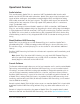
Apollo Twin Hardware Manual 29 PAD MIC/LINE SELECT INPUT GAIN 10 – 65 dB HI-Z/MIC HI-Z/MIC-LINE INPUT GAIN 10 – 65 dB SELECT SELECT A/D A/D DSP ø LOW-CUT POLARITY ON/OFF CONTROL DSP ø LOW-CUT POLARITY ON/OFF CONTROL APOLLO TWIN HARDWARE BLOCK DIAGRAM V06 THUNDERBOLT TM HOST INTERFACE OPTO OPTICAL INPUT 1/4” TRS LINE IN 2 1M PAD +48V +48V ON/OFF MIC PAD IN/OUT XLR FEMALE MIC IN 2 1/4” TRS LINE IN 1 1/4” HI-Z IN XLR FEMALE MIC IN 1 +48V +48V ON/OFF MIC PAD IN/OUT ANALOG INPUTS
Chapter 5: Notices Important Safety Information Before using this unit, be sure to carefully read the applicable items of these operating instructions and the safety suggestions. Afterwards, keep them handy for future reference. Take special care to follow the warnings indicated on the unit, as well as in the operating instructions. Water and Moisture – Do not use the unit near any source of water or in excessively moist environments.
Warranty Universal Audio provides a warranty on all hardware products. To learn more, please visit www.uaudio.com/support/warranty.html or contact Technical Support. This limited warranty gives you specific legal rights. You may also have other rights which vary by state or country. Maintenance Apollo 8 does not contain a fuse or any other user-replaceable parts. The unit is internally calibrated at the factory. No internal user adjustments are available.
Disclaimer The information contained in this manual is subject to change without notice. Universal Audio, Inc. makes no warranties of any kind with regard to this manual, including, but not limited to, the implied warranties of merchantability and fitness for a particular purpose. Universal Audio, Inc. shall not be liable for errors contained herein or direct, indirect, special, incidental, or consequential damages in connection with the furnishing, performance, or use of this material.
Universal Audio, Inc. 4585 Scotts Valley Drive Scotts Valley, CA 95066 USA Customer Service & Technical Support: USA Toll-Free: +1-877-698-2834 International: +1-831-440-1176 www.uaudio.