
Installation Instructions
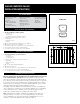
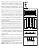
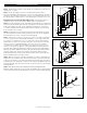


fig. 7
PostDetail.pdf
Step 2 Install railing posts prior to installing deck boards. Cedar or pressure-
treated pine 4x4 railing posts or a post mount provides the structural strength
for the railing. The length of each post is determined by the total of the joist
width (typically 7-1/4”) + decking thickness (1”) + railing height (36”) + spacing
for post cap (1-1/4”) = 45-1/2”. Important: Do not notch the 4x4 railing posts.
Notching will reduce the strength of the post and could result in railing collapse
or failure (fig. 3).
Step 3 Position, plumb with a level, and clamp the railing post on the interior
face of the joist. Plumb again. The 4x4 railing post should be bolted to the inside
of the joist using two 1/2" x 6" galvanized carriage bolts. Corner posts use a
third carriage bolt inserted through the adjacent joist (fig. 3).
Step 4 Install decking; notch deck boards to fit around the 4x4 railing posts.
Allow 1/4" space between the deck boards and any permanent structure or
post. Additional blocking may be necessary on the 4x4 for fastening deck
boards.
Step 5 Trim 4x4 post sleeves to length. Post sleeves should be a minimum
of 1-1/2” longer than the railing height (fig. 4). Example: For a 36” high railing,
trim post sleeve to a minimum of 37-1/2”, can be left longer if desired. Slide a
trimmed post sleeve over each 4x4 railing post. Post sleeve should slide easily
over the post. DO NOT FORCE post sleeve onto post. Twisted or crooked 4x4s
should be replaced. Slide a post base trim (optional) over each post sleeve for
a finished look. Note: It is recommended to install the post base trim prior
to installing the bottom rail. However, the two-piece design does allow the
installer to add the post base trim after the rail has been installed. To install,
apply a thin line of clear exterior construction adhesive to the inside of the
post trim, where it will contact the post sleeve, and snap into place around
the base of the post sleeve.
Step 6 Measure the distance between installed post sleeves to determine
the length of the top and bottom rails. Place the bottom rail in position next to
the posts and adjust so the distance between the first baluster hole and post
is greater than 2" and equal on both ends (refer to fig. 5). Mark the rail. Cut the
bottom rail. Cut the top rail to the same spacing and length.
Step 7 Find the center of the underside of the bottom rail and attach the
baluster connector included with the support block using the screw provided.
Check building code requirements for the maximum spacing between deck
surface and bottom of rail (sweep); we recommend 3" but it can be less if
desired. If necessary, trim the support block to the determined height (fig. 6).
Step 8 Place the line rail bracket covers and line brackets on the ends of the
bottom rail. Install the support block and prop the bottom rail between the
posts using blocks cut to size. Check the rail for level. Using the line bracket
as a guide, mark the screw positions on the post sleeve and rail on both ends.
Pre-drill 1/8” pilot holes through the post sleeve and rail. Attach the line bracket
to the post sleeve using the #8-15 x 2” - #2 square drive pan head screws and
then attach line bracket to rail using #10-16 x ¾” - #2 square drive pan head
self-drilling screws (fig. 5).
Step 9 Place a baluster over each baluster connector on the bottom rail. Make
sure baluster is fully seated in connector. Gently tap with a rubber mallet, if
needed.
Step 10 Place the line rail bracket covers and line brackets on the ends of
the top rail. Position the top rail by placing the baluster connectors inside the
balusters, while working from one end to the other. Check the rail for level.
Using the line bracket as a guide, mark the screw positions on the post sleeve
and rail on both ends. Pre-drill 1/8” pilot holes through the post sleeve and rail.
Attach the line bracket to the post sleeve using the #8-15 x 2” - #2 square drive
pan head screws and then attach line bracket to rail using #10-16 x ¾” - #2
square drive pan head self-drilling screws (fig. 5).
Step 11 Slide the rail bracket cover over the rail bracket and snap into place.
Step 12 Apply a thin line of clear exterior construction adhesive to the inside rim
of a post cap and place firmly on the post. Repeat for each post.
fig. 3
LevelRailAsm.pdf
Top Rail Bracket
and Bracket Cover
Bottom Rail Bracket
and Bracket Cover
Baluster
Connector
Top Rail
Post
Cap
Post
Sleeve
Post
Base
Trim
Support
Block
Bottom Rail
Baluster
•
•
•
•
•
•
•
•
•
•
LevelRailInst.pdf
3" Sweep
Support Block
Bottom Rail Bracket
and Bracket Cover
Equal spacing on both ends
Baluster
Connector
Baluster
•
•
• •
•
•
•
•
fig. 5
CTXConn.ai
Baluster
Connector
Bottom Rail
•
•
fig. 6
fig. 4