
User's Manual


Universal Scientific Industrial Corp..
Doc No.
Rev
1.1
Document released by WP/RD/WM/HW1 Date.
2015-05-04
Page
3
Description
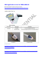
WM-N-BM-30 Application Note
The content of this document is to be treated as strictly confidential and is not to be disclosed, reproduced or used, except as authorized
in writing by Universal Scientific Industrial Co., Ltd. Copyright © 2011 Universal Scientific Industrial Co. ,Ltd.
3
1.
Characteristic Option
1.1
Boot mode
At startup, boot pins are used to select one out of three boot options:
Boot from user Flash
Boot from system memory
Boot from embedded SRAM
The boot loader is located in system memory. It is used to reprogram the Flash memory by
using USART1(PA9/10), USART2(PD5/6), USB OTG FS in device mode (PA11/12) through
DFU (device firmware upgrade), I2C1(PB6/7), I2C2(PB10/3), I2C3(PA8/PB4),
SPI1(PA4/5/6/7), SPI2(PB12/13/14/15) or SPI3(PA15, PC10/11/12).
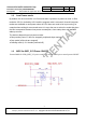
Low
Boot from user Flash
BOOT0
High
Boot from system memory / embedded SRAM
JP1
Header1x2
12
VDD_3V3
BOOT PIN
BOOT PIN
R1
10k
WM-N-BM-30 set the BOOT0 to GND, the Boot mode is Main Flash memory. When BOOT0
set to High, the BOOT mode is system memory.