STENCILING & MARKING SYSTEMS OWNER’S MANUAL NON-POROUS CONVEYOR LINE PRINTERS ALL MODELS INSTALLATION - OPERATION - MAINTENANCE UNIVERSAL STENCILING & MARKING SYSTEMS, INC. P.O. BOX 871 - ST. PETERSBURG, FLORIDA 33731 USA PH: (727) 894-3027 FAX: (727) 821-7944 E-Mail: sales@universal-marking.com Website: www.universal-marking.
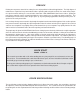
IMPORTANT NOTE UNIVERSAL products are manufactured to exacting standards and every available step has been taken to assure your complete satisfaction. It is most important, however, that the instructions contained in this manual are read and carefully followed for best results. Failure to do so may result in unsatisfactory performance, damage to the equipment and personal injury.
PREFACE Printing on non-porous materials has always been a major problem in industrial applications. The high degree of maintenance required to keep conventional coders operating with solvent based inks has made many companies opt for manual marking as a cost effective alternative. With UNIVERSAL Non-Porous Coders, printing on non-porous materials can be accomplished with the same relative ease as printing on porous materials.
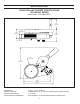
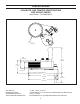
SPECIFICATIONS CONVEYOR LINE PRINTER SPECIFICATIONS TOP MOUNT SERIES Model Shown: CLP-100NI-NPRT 8.25 (209.55 MM) 1.56 3.90 (39.62 MM) 4.93 (99.06 MM) (125.22 MM) 1.13 (28.70 MM) 5.75 11.89 1 2 (302.01 MM) N MI 3 X MA (146.05 MM) 10.51 (266.95 MM) 11.50 (292.10 MM) NET WEIGHT: MAXIMUM DIE SIZE: MAXIMUM PRINT WIDTH: PRINT DRUM CIRCUMFERENCE: 10 LBS. - 12 OZS. (4.88 KG.) 7 RIBS WIDE X 16-15/16" LENGTH (7 RIBS WIDE X 430 MM LENGTH) 1" (25.
SPECIFICATIONS CONVEYOR LINE PRINTER SPECIFICATIONS SIDE MOUNT SERIES 3 2 MI N 1 MA X Model Shown: CLP-200NI-NPLS 5.75 (146.05 MM) 2.49 (63.25 MM) 9.80 (248.92 MM) 4.80 (121.92 MM) 2.00 (50.80 MM) 11.25 (285.75 MM) 8.25 (209.55 MM) 11.50 (292.10 MM) NET WEIGHT: MAXIMUM DIE SIZE: MAXIMUM PRINT WIDTH: PRINT DRUM CIRCUMFERENCE: 11 LBS. -5 OZS. (5.13 KG.) 14 RIBS WIDE X 16-15/16" LENGTH (14 RIBS WIDE X 430 MM LENGTH) 1.875" ( 47.
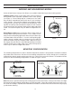
SPECIFICATIONS INDEXING AND NON-INDEXING MODELS Universal Non-Porous Conveyor Line Printers are available in both indexing and non-indexing models. Indexing coders contain a print drum spring return mechanism which provides print registration capabilities when carton printing (see Figure 1). As the trailing edge of a carton passes the coder, the print drum automatically rotates back to the same starting or “home” position.
SPECIFICATIONS RIBtype® PRINTING DIES ® Universal Non-Porous Coders are designed to use Universal RIBtype rubber type, printing dies which have a molded rib backing. The ribs ® on the back of the die snap into mating ribs in the RIBtype Drum Cover on the print drum as shown in Figure 4. ® Universal RIBtype dies are available in many standard character styles and sizes.
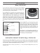
SPECIFICATIONS INK ROLLS Universal offers two ink roll options for the Non-Porous Conveyor Line Printers each with unique characteristics which will help determine the suitability for a specific printing application. The coders are designed to accommodate both types of ink rolls without modification. A detailed review of your printing requirements will determine the best choice of ink rolls for your particular application.
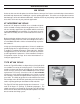
QUICK START INSTALLING THE INKING SYSTEM ASSEMBLY Your new Non-Porous Conveyor Line Printer was fully assembled and adjusted at the factory before final inspection. In order to minimize the size of the shipping cartons used to package these machines, the Non-Porous Inking System Assembly was removed from the Pivot Arm and must be reinstalled before operation. 1 -To install the Inking System Assembly “A” remove the (2) Mounting Screws “B” from the bottom of the assembly.
QUICK START 5 - Press the Inking System Assembly towards the Print Drum and adjust the Position Adjusting Screw “F” until the Knurled Drive Wheel “G” makes positive contact with the Friction Bearer “H” on the Print Drum. When the Pivot Arm Adjustment Knob “C” is tightened, the Knurled Drive Wheel should only contact the Friction Bearer Ring with enough pressure to drive positively when the print drum is rotated. This adjustment procedure also controls the Transfer Roll contact with the printing dies.
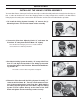
QUICK START 3 -While holding the Knurled Drive Wheel Cover “J” in place, remove the Knurled Cover Retaining Knob “K” by turning it counter-clockwise. The Cover Retaining Knob holds the entire inking system together and other parts may fall free from the coder if not held securely when this knob is removed. FIGURE 15 4 -Hold the Inking System Cover “L” in place and remove the Knurled Drive Wheel Cover “J”. The Knurled Drive Wheel Cover is very loose fitting.
QUICK START 7 -Put on a pair of rubber gloves and remove the pre-inked ink roller from the storage container by inserting a small rod (a pencil works nicely) in the center of the core. Keeping ink off your gloves at this stage will prevent contamination of the external parts of the coder during roll installation. FIGURE 19 8 -Inspect the roll for excess surface wetness. Remove any excess ink by rolling the roll lightly over a piece of absorbent paper.
QUICK START 11 -Replace the Knurled Drive Wheel “G” by aligning the 3 small holes with the 3 stainless drive pins on the top of the Transfer Roll “N” and pressing the Drive Wheel onto the Transfer Roll. The tops of the stainless pins will be flush with the top of the Drive Wheel when seated properly. FIGURE 23 12 - Replace the Knurled Drive Wheel Cover “J” and rotate it into position with the flat edge directly facing the Print Drum. Hold the Drive Wheel Cover and Inking System Cover in place.
QUICK START INSTALLING THE PRINTING DIES 1 - Align the ribbed backing on the Printing Dies “P” with the mating Drum covering on the Print Drum “D” and press firmly until they are completely engaged. It is best to install the dies as close to the middle of the print area on the Print Drum as possible. Individual character codes or text messages are installed in a mirror image of normal written text. In other words install in a right to left direction as shown.
QUICK START ADJUSTING THE INK ROLL ECCENTRIC 1 - After the printing dies are installed on the print drum, manually rotate the print drum continuously in one direction while slowly rotating the Ink Roll Eccentric Adjusting Knob “I” from the “MIN” position towards the “MAX” position. Turn the Eccentric Knob in small increments and observe the face of the Printing Dies “P” for signs of ink between each adjustment. As soon as you can see complete ink coverage on the die faces, stop rotating the eccentric.
BASIC PRINCIPLES OF OPERATION NON-POROUS INKING SYSTEM Inks designed for printing on non-porous surfaces contain very fast drying alcohol solvents, a component to impart color which can be either a liquid “dye” or a finely ground solid or “pigment”, and a resin material which binds the color medium to the material surface. When the printed marks are applied by the coder, the solvents rapidly evaporate from the surface of the material leaving only the dried resin and color.
BASIC PRINCIPLES OF OPERATION When a Reservoir Ink Cartridge is threaded into the bottle port, the plastic ball in the cartridge comes into contact with the surface of the neoprene ink roll. When the ink roll rotates during the printing operation, a thin film of ink is transferred from the reservoir cartridge onto the surface of the ink roll. The printed impressions will improve within a few seconds after installation of the cartridge.
BASIC PRINCIPLES OF OPERATION INK DRYING TIME CONSIDERATIONS Depending on the specific characteristics of the printing application, some consideration needs to be given to the drying time of the ink and its suitability for the application. Printing on a plastic film in an intermittent motion Form and Fill Machine may require a slower drying ink formulation than that recommended for high speed continuous web printing applications.
WEB PRINTING This section applies to the installation of the Non-Porous Conveyor Line Printers for printing on continuous web materials such as plastic films, rubber sheeting, metals and other extruded materials. Careful consideration should be given to selecting an appropriate area in the production line for installation of the coder.
WEB PRINTING In high speed web applications, the distance the web travels at a given speed in 2-3 seconds can be substantial. It is important to note that when the printed web is tightly rewound, the additional pressure applied to the printed marks can increase the possibility of a ghost image transfer of the ink to the back of the web.
WEB PRINTING DO NOT INSTALL A 4 oz. RESERVOIR INK CARTRIDGE AT THIS TIME. The coder is designed to print using the ink contained in the pre-inked ink roll. Since a freshly saturated Ink Roll was just installed on the coder, the system will have plenty of ink. Installing a 4 oz. Reservoir Ink Cartridge immediately will result in over saturation of the ink roll and flooding of the Inking System. The 4 oz.
WEB PRINTING GANG MOUNTING In web printing applications where multiple coders are required to be mounted across the web, Universal offers special mounting hardware which facilitates gang mounting the coders as indicated in Figure 38. In these installations, special CLP-SBA Saddle Mount Bracket Assemblies are used in conjunction with an extruded structural aluminum mounting bridge. The 1.5" x 3.
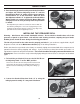
CARTON PRINTING Printing on non-porous surfaces, such as waxed or varnished cartons, can be accomplished easily with Universal Non-Porous Conveyor Line Printers. The selection of an appropriate place for installation on your conveyor line or other packaging equipment is a very important consideration in the performance of your coder. The most important factor to consider is carton alignment.
CARTON PRINTING Universal Non-Porous Conveyor Line Printers are designed so the frame of the machine will pivot on the mounting column. This allows the print drum to deflect, or swing, on contact with the leading edge of the carton a maximum of 2". It is recommended that cartons be aligned between guide rails with no more than 1/4" clearance on each side as shown in Figure 40. This should allow ample clearance for cartons and protect your printer from damage.
CARTON PRINTING Loosen the mounting column clamping bolt (Figure 43) and position the printer to the required height for printing. Swing the printer into position so that the print drum will lightly contact the side of the cartons as they emerge from between the guide rails. Check the print drum contact with the cartons while the conveyor is under power and adjust the print drum position to obtain approximately 1/4" - 3/8" deflection (Figure 44).
CARTON PRINTING Although installing the printing dies in this position restricts how close to the leading edge of the carton you can register the print, it is one of the only ways to ensure a good imprint on every carton. Since the fastest drying nonporous inks will dry in approximately 2 seconds at 75 Degree F. ambient temperature, the ink will also dry on the die face within 2 seconds after it is applied by the transfer roll.
MAINTENANCE PRE-INKING A NEW INK ROLL When you are ready to begin printing, you must first install an ink roll which has been properly pre-inked with the appropriate non-porous ink. Unless you ordered a pre-inked roll with your machine, you will find a dry roll in a plastic container with your coder. Note: Dry rolls cannot be inked automatically using the 4 Oz. Reservoir Ink Cartridges. Warning: Non-Porous Inks contain flammable solvents.
MAINTENANCE CLEANING THE TRANSFER ROLL The surface of the transfer roll is made from DuPont Delrin material and the O.D. of the roll is finely engraved which enables it to hold a uniform film of ink. This surface material is very fragile and under no circumstances should you attempt to clean it with anything abrasive. Warning: Most of the ink solvents used for cleaning are flammable liquids. Follow all safety precautions recommended by the manufacturer during this process.
MAINTENANCE CLEANING THE PRINTING DIES All inks which are formulated for printing on non-porous surfaces contain a resin binder which bonds the dye or pigment in the ink to the surface of the material being printed. As the ink begins to dry, this binder becomes “tacky” or “sticky”. While in this stage of the drying process, the tack on the printing dies will tend to pick up both airborne dust and any dust or dirt on the surface of the material being printed.
MAINTENANCE MOUNTING CONFIGURATION CONVERSION LEFTHAND/RIGHTHAND FIELD CONVERSION Mounting configuration conversion involves the “mirror image” reversal of the pivot arm assembly that holds the inking system and the tension arm assembly which provides the printing pressure. Indexing printers require the additional reversal of the index ramp and repositioning of the index ring. Universal Non-Porous CLP Coders are assembled at the factory for either right-hand or left-hand mounting.
MAINTENANCE SET SCREW POSITION FOR LEFT HAND MOUNT SET SCREW POSITION FOR RIGHT HAND MOUNT 10 -Reinstall the Inking System Assembly and adjust as explained on Page 9 - Installing the Inking System Assembly. BOTTOM VIEW OF INKING SYSTEM BASEPLATE FIGURE 55 TENSION ARM ASSEMBLY CONVERSION 1- Loosen the Lock Nut and screw the Adjusting Bolt in to relieve the spring pressure (Figure 56). 2- Remove the spring by lifting the end off the Locating Button.
MAINTENANCE PRINT DRUM INDEX MECHANISM CONVERSION 1- Using a 5/64” hex wrench, loosen the Nylon Tip Set Screw located in the top rim of the Print Drum. FIGURE 57 2- Remove the Print Drum Dust Cover. FIGURE 58 3- To relieve the spring tension on the index mechanism, rotate the Print Drum approximately 3/4 turn. The Index Compression Springs will now be in the fully extended (relaxed) position.
MAINTENANCE 5- Using a 1/8" hex wrench, loosen the Brass Tipped Set Screw located in the side of the Index Ring until the Index Ring rotates freely. PRINT DRUM AXLE RECESS AREA .04 BRASS TIP SET SCREW FIGURE 61 Important Note: The Print Drum Axle is machined with thread relief as shown in Figure 40 so the tip of the set screw will not damage the threads. To completely remove the Index Ring from the Axle, the Brass Tip Set Screw must be loosened at least 2 full turns to prevent damage to the threads.
MAINTENANCE 8- Reinstall the Index Ramp in the proper orientation for your mounting configuration as shown in Figures 64 & 65. LEFT HAND CONFIGURATION RIGHT HAND CONFIGURATION FIGURE 65 FIGURE 64 REPLACING PRINT DRUM INDEX SPRINGS 1- To replace Print Drum Index Springs, rotate the Print Drum approximately 3/4 turn to relieve spring tension as shown in Figure 59, Page 32. 2- Using a small screwdriver, remove the two Snap Rings on the Index Spring Assembly.
MAINTENANCE 4- Holding onto the Index Assembly Block “A”, pull the Index Assembly Block “C” off the guide shafts (Figure 68). Remove the Drum Index Springs (Figure 69) FIGURE 69 FIGURE 68 5- Install new Index Springs over the stainless steel guide shafts and replace Index Block “C”. Ensure that Block “C” is installed in the same orientation as Block “A” with the flange of the white bushing (the large diameter end) facing in the same direction.
MAINTENANCE 2- Lift Index Block “B” straight up to remove. The head of the Index Assembly Mounting Screw engages the TSlot in Index Block “B”. This mounting design facilitates height adjustment of the Index Block during reassembly. FIGURE 71 Before replacing Index Block “B”, ensure that the Index Ring is properly adjusted as explained in Steps 5 - 7 on Page 33.
MAINTENANCE INKING SYSTEM ASSEMBLY The following steps will guide you through the Ink Roll Eccentric Assembly. 1 - Install the O-Ring in the groove of the Eccentric flange, then install one of the white delrin washers on the Eccentric. ECCENTRIC O-RING FIGURE 74 2 - Apply a thin coating of grease to the O-Ring and the Eccentric to approximately 1/2” from the flange. Automotive wheel bearing grease is recommended. FIGURE 75 3 - Insert the Eccentric into the Inking System Cover.
MAINTENANCE 5 - Install the Eccentric Knurled Knob and align the engraved line on the knob with the “MAX” line on the Inking System Cover. Set the ink roller axle on a small block of wood or metal . The block used should be tall enough so the entire assembly is supported by the ink roller axle (the Inking System Cover should not touch the table top). FIGURE 78 6 - Press down firmly on the Eccentric Knurled Knob. While holding pressure on the knob, tighten the two set screws.
NON-POROUS CONVEYOR LINE PRINTER CE GUARD ASSEMBLY 6 5 4 1 2 3 NON-POROUS CONVEYOR LINE PRINTER CE GUARD ASSEMBLY PARTS LIST KEY NO. PART NUMBER QTY. REQD.
NON-POROUS CONVEYOR LINE PRINTER ASSEMBLY 29 1 28 2 27 3 4 26 7 25 6 8 5 23 9 24 14 13 15 23 16 22 10 11 17 12 18 21 19 20 40
NON-POROUS CONVEYOR LINE PRINTER PARTS LIST DESCRIPTION KEY NO. PART NUMBER QTY. REQD. 1 CM-04 1 KNURLED RETAINING RING 2 CF-05 1 SET SCREW, 8-32 X 3/16” S.S.
NON-POROUS CONVEYOR LINE PRINTER INKING SYSTEM ASSEMBLY 1 2 20 3 4 19 18 5 17 6 16 15 7 14 13 8 9 10 11 12 42
NON-POROUS CONVEYOR LINE PRINTER INKING SYSTEM PARTS LIST DESCRIPTION KEY NO. PART NUMBER QTY. REQD.
NON-POROUS CONVEYOR LINE PRINTER PRINT DRUM ASSEMBLY 1 2 4 3 NON-POROUS CONVEYOR LINE PRINTER PRINT DRUM ASSEMBLY PARTS LIST KEY NO. PART NUMBER QTY. REQD.
NON-POROUS CONVEYOR LINE PRINTER INDEX ASSEMBLY 11 1 10 2 9 3 4 5 7 6 8 NON-POROUS CONVEYOR LINE PRINTER INDEX ASSEMBLY PARTS LIST DESCRIPTION KEY NO. PART NUMBER QTY. REQD.