
- Universal printer MAINTENANCE OWNER'S MANUAL

30
MAINTENANCE
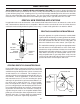
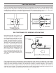
Mounting configuration conversion involves the “mirror image” reversal of the pivot arm assembly that holds the
inking system and the tension arm assembly which provides the printing pressure. Indexing printers require the
additional reversal of the index ramp and repositioning of the index ring.
Universal Non-Porous CLP Coders are assembled at the factory for either right-hand or left-hand mounting. If
field conversion is required, the following steps will guide you through the conversion process.
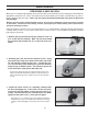
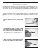
1- Loosen the Pivot Arm Adjustment Knob and rotate the Inking System away from the Print Drum slightly.
2- Remove the Inking System Assembly from the coder by removing the 2 socket head cap screws on
the underneath side of the Pivot Arm.
3- Remove the Pivot Screw and lift the tension adjustment assembly off of the coder.
4- Remove the Pivot Arm Cap and lift the Pivot Arm assembly off it’s axle.
5- Reinstall the Pivot Arm on the axle in the opposite or “mirrored” orientation and replace the Pivot
Arm Cap.
6- Remove the Position Adjusting Screw and reinstall in the reverse position.
7- Replace the tension adjusting assembly and the Pivot Screw.
LEFTHAND/RIGHTHAND FIELD CONVERSION
PIVOT ARM & INKING SYSTEM ASSEMBLY CONVERSION
FIGURE 54
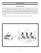
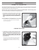
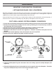
8 - Remove the Baseplate Plug from the bottom side of the Inking System Assembly Baseplate (See
Figure 55).
9 - Reinstall the Baseplate Plug in the threaded hole on the opposite side of the Baseplate. Thread the
Plug into the Baseplate only until the flush with the Baseplate surface.
PIVOT SCREW
PIVOT ARM CAP
LEFT HAND
CONFIGURATION
RIGHT HAND
CONFIGURATION
POSITION ADJUSTING
SCREW
PIVOT ARM
ADJUSTMENT KNOB
INKING SYSTEM
ASSEMBLY
PIVOT ARM
TENSION
ADJUSTMENT
ASSEMBLY
MOUNTING CONFIGURATION CONVERSION