Table Of Contents This User Guide has been edited for content.
Chapter 2 - Safety 8
Description of Appropriate Use This device is designed for laser cutting and engraving in an office, laboratory, workshop or light duty manufacturing environment. Materials to be processed must fit completely inside the system for proper operation.
DANGEROUS VOLTAGES ARE PRESENT WITHIN THE ELECTRONICSENCLOSURES OF THIS SYSTEM. Access to these areas is not necessary during normal operation. If it becomes necessary to open one of these enclosures for service reasons, please remember to disconnect the power cord from your electrical supply. NEVER REMOVE THE GROUND LEAD TO THE ELECTRICAL CORD AND PLUG THE SYSTEM INTO A NON-GROUNDED OUTLET.
Chapter 4 - Operation NOTES: We reccomend the Manual Printer Driver Interface (page 56) over the Materials Database Printer Driver Interface that is recommended in the user guide. We also recommend the manual focusing option (page 78) over any of the others. Adobe Illustrator files must be set in RGB Document Mode as well as the RGB color pallet. Values for Illustrator colors are on page 80.
Important Overview CAUTION: Please refer to the Safety section before operating the laser system. All ULS laser systems are designed to operate like a computer printer. The laser systems are provided with two software components designed for Microsoft Windows based operating systems. The first component is a printer driver that allows you to print from any Windows based graphic software capable of printing through the Windows print system.
The Printer Driver Interface The printer driver is a piece of software that allows you to create jobs for the laser system using the Windows print system. The printer driver has a preferences dialog with two tabs which allow you to set various parameters for a print job. One tab offers a materials-based approach to setting job parameters and the other offers a more detailed manual approach to setting job parameters.
Define Job (material only) Add a sub-material record underneath the main record. This sub-material record captures all user-defined settings in the materials tab GUI which are normally not part of a standard material record, including fixture type, material thickness, printing direction, vector sliders and intensity adjustments. Hide Hide the selected material or category. This function is useful to hide materials which you do not commonly process. To un-hide materials, push CTRL-F2.
3D mode: This mode affects raster elements of your image. In this mode, instead of a dither pattern being applied to all raster data, the laser power level is varied on the fly in accordance with the grayscale levels in the image (multicolor bitmaps are converted to grayscale first). Lighter parts of the image will receive less laser power and darker parts more laser power. This mode is for very specific applications.
Fixture Type None If you are not using any type of fixture, set the drop down menu to NONE. Rotary If you have purchased this accessory, read how to install and operate this fixture in the Accessories section of the User Guide. Pin Table If you have purchased this accessory, read how to install and operate this fixture in the Accessories section of the User Guide.
Can be Vector Cut Select this switch if the material can be cut and enter information in the vector cut section. Fixed Thickness Select this switch if the material being added is only available in a particular thickness and you want to lock the thickness to one value. Stamp Support Select this switch if the material supports rubber stamp mode.
Apply Button The APPLY button saves all changes made to the printer driver settings. Default Button The Default button will reset the driver settings to factory default values. You may abort these changes by selecting Cancel; selecting OK or APPLY will approve the changes. Load Button To recall a snapshot of the printer driver settings that have been previously saved to a .LAS file using the save button, select on the “Load” button and choose the desired .LAS settings file from the dialog box.
Manual Printer Driver Interface Tab (advanced users) This tab of the printer driver is for the advanced user and allows the user to manually configure all laser job settings. This approach allows the user much more configurability, but requires a deeper knowledge of the laser job settings and how they affect laser processing. Please note that when this tab is used laser settings are applied to the graphic being printed by color and each color can contain raster and vector data.
that there is no difference in the depth of cut from straight lines to curves. % Power and % Speed work together in determining how deep the engraving or cutting will be. Higher power and slower speeds produce deeper results. Lower power and higher speeds produce shallower results. Note: 100% raster speed is different than 100% vector speed. Rastering is done with the X axis focus carriage which is light weight and has a high acceleration and top speed.
Z-Axis This control lets you set the Z-Axis table to a specific height. When the auto Z feature is turned on in the UCP and a Z height is set for a color in the color table, the table moves to the height indicated before processing the elements in the print job graphic that were mapped to that color. This feature can be used as a method of focusing by entering the thickness of the material to be processed.
Raster Sub-Tab The raster sub-tab on the manual control tab of the printer driver setting interface displays a group of settings which affect how raster objects are processed by the laser system. The controls in the sub-tab are described below: Print Special Effects The drop down list allows you to choose from several special print modes, normal for most materials and applications or one of the other modes for special applications.
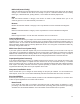
Rubber stamp mode This mode is specifically for rubber stamp creation and is E n g ra v e d O r ig in a l used for creating shoulders on characters and graphics R e s u lt G r a p h ic when processing rubber stamps. The shoulder is created by gradually ramping the laser power up or down near the N e g a t i v e edges of each element in the graphic being printed creating I m a g e a tapered edge around each graphic element that produces a pyramid-like effect in the material being processed.
Power The Power table graphically represents the shoulder characteristics of the predefined rubber stamp shoulders and also allows you to adjust the shape of any custom shoulders you create. You will notice that you cannot adjust the settings when a predefined shoulder is selected. You must press the new button to create a clone of the selected shoulder and then you will be able to edit the settings for the cloned shoulder.
1-Touch Laser Photo Switch This switch is automatically selected when printing photos from Universal Laser Systems 1-touch Photo laser photo printing software. This switch also be selected when printing a photo processed by 1-Touch Photo and then imported into other software before printing. This switch optimizes settings for best results with 1-Touch Photo images.
Dithering Dithering settings are used when printing graphics that contain grayscale or color bitmaps such as photographs in all printing modes except 3D mode. A dither pattern is a special screen filter that is used to convert a grayscale or color image to monochrome (black and white). The screen filter reduces the image to black and white while preserving the illusion of shades of gray by varying the spacing of pixels (dots) in the image.
Image Enhancements This section contains settings for enhancing and improving raster imaging. Texturize Texturize is a special feature which adds random variation to the laser power level assigned to each color. This is useful for creating a textured effect on engraved surfaces to mask grain lines and motion artifacts. One useful application of this feature is when engraving away large areas of acrylic, but for most applications this feature is not necessary.
decelerating to change direction for the next raster stroke. If engraving or marking near the edges of the laser processing field these margins are automatically reduced. Automatic Enhancements Without Margins (Drop Down Menu) Decreases file completion times by removing over stroke margins. The laser system attempts to compensate for laser response while accelerating or decelerating to change directions for the next raster stroke but edge quality may suffer on some materials.
How to Tune Image Enhancement Settings These three parameters (CONTRAST, DEFINITION and DENSITY) work together to compensate for laser response when rastering at higher speeds. For a given material at a given speed they must be determined by testing. If you use the materials database, these values are already determined for you. You can look up these settings for a particular material in the database by selecting that material in the materials database tab and selecting edit.
Step 5: Establish the tuning value. Once the Contrast, Definition and Density are determined, an easy way to set the tuning value on a given material at a desired processing speed is to create a graphic consisting of about 20 thin vertical lines about 1” (25.4 mm) tall and .010” (.254 mm) apart in the center of the engraving field. The lines should have a line thickness of .001” (.0254 mm) if possible in the graphic application being used, otherwise use the thinnest the application allows.
scaling feature respectively. Keep in mind that this feature DOES NOT scale raster images. If you are combining raster and vector images in one file, the raster image may not align with your vectors. Raster objects cannot be scaled after printing. If it is necessary to scale raster objects, adjust their size in the graphic application you are using. Vector Performance There is a tradeoff between quality of output and speed of processing when printing vectors.
Merge Pages This setting allows you to treat multipage documents in different ways. By default, multipage documents are treated as separate jobs with each page having to be selected in the UCP and run individually. This setting allows you to change that behavior. Selecting this setting once will merge the pages with autostart, meaning the pages will all be printed one after another as one job.
The Universal Control Panel (UCP) When a graphic has been printed through the printer driver a laser job is created and passed to the queue in a piece of software called the Universal Control Panel (UCP). The UCP software provides a convenient interface for interacting with and controlling your laser system. Once you have installed the UCP, a red diamond-shaped icon will appear in the lower right corner of your Windows taskbar.
Focus View The Focus View allows you to quickly manually move the focus carriage to a desired position in the material processing field. • • • To have full range of motion, verify that you are zoomed out in the preview window by rightclicking on the mouse before entering the manual focus window. In the focus view the cursor changes to a blue target symbol with trailing X-Y coordinates. Pressing the mouse in the preview window moves the focus carriage to the selected position.
File Management As jobs are printed they are added to the print queue until the queue reaches the print queue limit set in the system tab. Once the Print queue reaches the maximum number of jobs, the printer driver deletes the oldest job each time a new job enters the queue (a FIFO system).
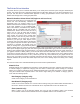
System Tab The System Tab allows you to configure certain features of the laser system. If your laser system needs to be calibrated, you will need to do so from this tab. The System tab contains the following controls • • The PRINT CACHE number indicates the maximum number of print jobs that will be stored on your hard drive.
• • If you would like the laser system to re-home the X and Y axes before it processes each job, select the ‘Home XY Before Engraving’ switch. Your laser system may contain an Air Pressure detection switch to warn you if no air pressure is present and you have selected air assist functions in the job properties window. If the DETECT AIR PRESSURE switch is selected and sufficient air pressure is not present, then an error message is displayed.
Control Panel The control panel on your laser system provides the functions necessary to setup and run jobs on your laser system. Safety Interlock Status A Red LED on the control panel provides an indication of the status of the interlock system. Indication Condition On All access doors to the laser system are closed. If a laser job is initiated in this state, the CO2 laser will fire. One or more of the access doors to the laser system is open and the safety interlock system has disabled the CO2 laser.
Display Main Menu: When your laser system is initially powered up the laser system model name will appear on the displayed. This screen will remain until the laser system establishes communication over the USB port with the Universal Control Panel running in the task bar on your PC. If the UCP is not running in the task bar or the laser system is not connected to a USB port on the PC, the laser system will not be able to function.
Loading and Processing Materials Before laser processing material, you will need to load material into the laser system and then focus the laser system onto the top surface of the material. Loading Material Open the top door to the laser system and place material to be laser processed onto the engraving table. You may need to manually move the support table down to allow clearance to fit thicker materials into the machine.
Focusing Once you have positioned the material, you will need to focus the laser system by adjusting the Z axis up or down until the top surface of the material to be laser processed is at the focal plane of the lens installed in the laser system. This can be done in one of four ways. The first focusing method is to use the calibrated focus tool provided with the lens kit. Every lens kit is provided with a calibrated focus tool so make sure to use the one provided with the lens being used.
A final focusing method is to use the auto-focus feature to focus on the material. In the Cell 2 and Cell 3 laser systems, the autofocus sensor is a light beam sensor that crosses the processing area horizontally at about 3” inches in the Y axis. There is a notch in the Y axis ruler between the 2” and 4” marks to indicate where the beam crosses the processing area. Make sure that a least at portion of the material to be processed is lined up vertically with the notch blocking the light beam.
Third-Party Graphic Software Configuration ULS Windows Printer Driver will work with a wide variety of Windows based graphic software to create laser jobs through the Windows Print System.
Vector Output for Vector Cutting and Marking The printer driver distinguishes between raster objects (raster engraving) and vector objects (vector cutting and marking) by the types of elements contained in the graphic being printed. All graphics, other than outlines of very thin line widths will be interpreted as raster objects and the raster mode will be used for laser processing. Not all software is capable of printing vector output.
AutoCAD and AutoCAD LT Note: AutoCAD version 2000 is not compatible with ULS laser systems. You must upgrade to version 2000i or higher. Vector output Line widths for printing from AutoCAD products are controlled by plot styles. Make sure you set the first eight pens in the plot style you use to .001” (.0254 mm) or less in order to ensure vector objects are output.
Chapter 5 – Accessories 83
Rotary Fixture The Rotary Fixture allows the laser system to engrave and mark on cylindrical objects. The Rotary fixture is equipped with an external cone shaped fixture mounted to the fixed, motorized end and an internal cone shaped fixture attached to the adjustable end allowing the fixture to hold a variety of objects such as wine glasses, mugs, cups, etc.
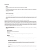
5. With the power to the system still OFF, connect the rotary fixture control cable to the receptacle on the laser system (6). Loading Material Before loading material into the fixture, measure the diameter (1) of the material in the area where the engraving or marking is to be located, by using a caliper or similar measuring device. A wine glass is used for illustrative purposes here. 6. Place the open end of the material (4) on the fixed end of the rotary fixture.
8. Power ON the laser system. If you are using the rotary for the first time or replaced the laser system’s CPU, rotary calibration may be needed, so proceed to the next step. If rotary calibration is not needed proceed to “Determining Graphic Placement.” Rotary Calibration 1. Select the System Tab of the UCP and press on the CALIBRATE button in the Rotary section. 2.
5. 6. 7. After focusing, press both SAVE buttons on the Rotary Calibration dialog. If asked to overwrite an existing position, accept the new value by pressing YES. Once complete, press the CLOSE button and the focus carriage will re-home. Calibration is now complete.
Determining Graphic Placement The next step is to align the graphics to be printed with the material inserted in the rotary fixture. Again, a wine glass is used for illustration. You can use the X axis ruler or to be more precise use the Red alignment Laser and the X-Y coordinate display in the UCP to position the graphics in the X axis. 1. Using the Navigation buttons on the UPC, position the Focus Carriage above the material. 2.
7. Once you have the new engraving field size, exit the printer driver properties dialog. 8. In your graphics software change the page size to equal the new engraving field size from the printer driver dialog. 9. This new vertical dimension of the page is now the circumference of the material to be engraved. 10. Position your graphic on page so that it is located horizontally within the upper and lower engraving limits that you determined earlier and center the graphic vertically as shown below. 11.
3. Once you are ready to print, select print in your graphics software and open the printer driver preferences dialog. In the materials driver tab select the material you are going to laser process, select “Rotary” in the fixture section and enter the diameter of the material measured earlier. 4. Finally, printing the job. Note: Remember, before running a rotary job, to rotate the material by hand until the position you want to be the center of your graphic is facing directly up.