MRF-260 Installation Manual Optimizing Narrow Band Reception with Complete Control Remotes COMPLETE CONTROL ™ Universal Remote Control®
MRF-260 Installation Manual ©2007 Universal Remote Control, Inc. The information in this manual is copyright protected. No part of this manual may be copied or reproduced in any form without prior written consent from Universal Remote Control, Inc. UNIVERSAL REMOTE CONTROL, INC. SHALL NOT BE LIABLE FOR OPERATIONAL, TECHNICAL OR EDITORIAL ERRORS/OMISSIONS MADE IN THIS MANUAL. The Home Theater installation on the cover was designed and installed by Stone-Glidden of King of Prussia and Doylestown, PA.
TABLE OF CONTENTS Introduction 1 Features and Benefits 2 Parts Guide 2 Installation 3 Testing 5 Front Blaster Overload 6 Disabling the Front Blaster - Step by Step via PC 6 Controlling Four Identical Components/Zones 7 Identical Components/Zones - Step by Step via PC 7 Programming For Multiple Equipment Locations 10 USA Limited Warranty Statement 11 Frequently Asked Questions 12 Specifications 12
MRF-260 BASE STATION Introduction The MRF-260 base station is an “addressable” base station. RF Addressing gives you the ability to control as many as 60 identical components throughout a house. To enable better range and reliability the MRF-260 is equipped with the Narrow Band RF reception (like the MRF-350), so is only compatible with other Narrow Band remotes.
MRF-260 BASE STATION Features and Benefits Interference Rejection and Extended Range via Narrow Band The MRF-260 receives RF (radio frequency) signals via its integrated RF receiver and antenna. The MRF-260 displays RF interference via a bright red Status LED, which flickers when interference is present if the ID is set to 0. Simply relocate the MRF-260 should interference occur. Two Fixed IR Outputs The MRF-260 is equipped with two fixed IR line outputs with standard 3.
MRF-260 BASE STATION Installation 1. Unplug the MRF-260. Test all IR commands and macros line of sight. 2. Power on all AV components including the TV. Turn on all of the lights and lower all dimmers to 50%. Power on anything that may create RF Interference (particularly devices with high speed microprocessors or hard drives). 3. Check that the address wheel on the rear of the MRF-260 is set to ID#0 (the interference “sniffing” position).
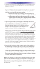
MRF-260 BASE STATION 5. Observe the Status LED of the MRF-260. If it is glowing or flickering you must relocate the MRF-260 to a location where the LED doesn’t flicker. If your installation location simply doesn’t offer you any choice and you are detecting interference everywhere you place the MRF-260, you have two last resort options: a. Remove the MRF-260’s antenna. This will reduce the range enormously, but may still be enough for this client. b.
MRF-260 BASE STATION Testing Test a few commands for each device before fixing the flasher in place on the front panel of a device. Since TiVo, Replay TV, Satellite Receivers and Cable Boxes are all extremely sensitive to IR overload or saturation, you should test them thoroughly. Put up the on screen guide and test the navigation arrows. Compare operation via RF to the original remote control. Operation should be identical. RF is not slower.
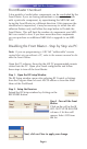
MRF-260 BASE STATION Front Blaster Overload A few models of audio/video components can be overloaded by the Front Blaster. If you are having intermittent or inconsistent results with a particular component, try repositioning the MRF-260 and facing the Front Blaster in a different direction. If this improves the situation but is impractical, it may be necessary to utilize the selfadhesive flashers only and follow the steps below to Disable the Front Blaster.
MRF-260 BASE STATION Controlling Four Identical Components/Zones There are several considerations to take into account when you are installing an MRF-260 to control an array of identical components: 1. The RF ID# cannot be set to Code 0, the universal setting. You must use one of the fifteen unique IR Routing addresses. 2. Each identical component must receive IR commands ONLY from a dedicated Flasher affixed to its front panel or a rear panel direct IR input.
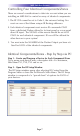
MRF-260 BASE STATION By looking at the Signal column, you can see that the factory default programming sets all of the devices to send both IR and RF commands. If you look at the column for Flashers, you can see that the default sends IR commands for all devices to ALL of the flashers. Both options must be changed for identical components. Additionally, you must disable the Front Blaster (see page 6 for directions).
MRF-260 BASE STATION In the figure below, each device is set to a specific flasher. Note: Remember, the MRF-260 will only respond to selections 1 through 4. Step 5 - Make sure that the ID# is set on both the remote and on the wheel of the MRF-260. Click on the Receivers button and set the RF address to one of the first 15 addresses (1-9 or A, B, C, D or E). The second set of addresses is only supported by MSC units. Step 6 - Close the RF window and Download to the Remote.
MRF-260 BASE STATION Programming For Multiple Equipment Locations You can operate up to 15 different equipment locations, each with an MRF-260 assigned a unique Receiver ID#. You program each of your remotes to talk to the equipment locations you want by assigning each of your devices to a receiver.
MRF-260 BASE STATION USA Limited Warranty Statement Your Universal Remote Control, when delivered to you in new condition, is warranted against defects in materials or workmanship as follows: UNIVERSAL REMOTE CONTROL, INC. warrants this product against defects in material or workmanship for a period of one (1) year and as set forth below.
MRF-260 BASE STATION Frequently Asked Questions Can I use flasher/emitters that I have already installed in the system to connect to the MRF-260? Yes, the flashers are compatible if they use 3.5mm mono mini plugs with the same polarity (Tip is data, sleeve is ground). I’m getting inconsistent operation regardless of flasher level or position. Some components are easily overloaded with IR from nearby flashers.
Information To The User This equipment has been tested and found to comply with the limits for a Class B digital device, pursuant to part 15 of the FCC Rules. These limits are designed to provide reasonable protection against harmful interference in a residential installation. This equipment generates, uses and can radiate radio frequency energy and, if not installed and used in accordance with the instructions, may cause harmful interference to radio communications.