MRF-300 Manual.qxd 1/14/2005 12:40 PM Page 1 MRF-300/RFX150 INSTALLATION MANUAL Multi-Zone RF Base Station for the MX-3000, the AuroraTM, the AerosTM, the Omega TM and the OsirisTM remote controls.
MRF-300 Manual.qxd 1/14/2005 12:40 PM Page 2 MRF-300 Installation Manual ©2005 Universal Remote Control, Inc. The information in this manual is copyright protected. No part of this manual may be copied or reproduced in any form without prior written consent from Universal Remote Control, Inc. UNIVERSAL REMOTE CONTROL, INC. SHALL NOT BE LIABLE FOR OPERATIONAL,TECHNICAL OR EDITORIAL ERRORS/OMISSIONS MADE IN THIS MANUAL. The information in this manual may be subject to change without prior notice.
MRF-300 Manual.
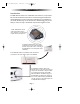
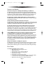
MRF-300 Manual.qxd 1/14/2005 12:40 PM Page 1 MRF-300 BASE STATION Introduction The MRF-300 base station is an “addressable” base station. It is only compatible with Universal Remote Control’s line of Custom Programmed Remotes with RF Addressing such as the MX-3000, the MX-950 Aurora, the MX-850 Aeros, the MX-800, MX-650 Omega and the MX-350 Osiris. RF Addressing gives you the ability to control as many as 90 identical components throughout a house. 1.
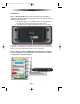
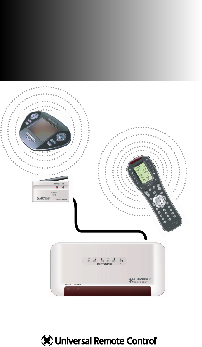
MRF-300 Manual.qxd 1/14/2005 12:40 PM Page 2 MRF-300 BASE STATION Features and Benefits Interference Rejection and Adjustable RF Range via RFX-150 The MRF-300 receives RF (radio frequency) signals via the RFX-150 RF Sensor. The RFX-150 displays RF interference via a bright RED LED, which flickers when interference is present. Simply relocate the RFX-150 out of the interference or reduce the range to eliminate interference via the RF Range adjust screw.
MRF-300 Manual.qxd 1/14/2005 12:40 PM Page 3 MRF-300 BASE STATION Installation Step 1 - Set the RF ID # rotary switch on the bottom of the MRF-300 to a VALID ID# (any address other than ID# 0). If you leave it set to ID# 0, the MRF-300 operates with some restrictions: a. Accepts RF signals from any 418MHZ remote control regardless of the address set when programming the remote control. b. Front Blaster will be OFF and all IR line outputs are set to ALL).
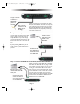
MRF-300 Manual.qxd 1/14/2005 12:40 PM Page 4 MRF-300 BASE STATION Copper colored conductor is GROUND (Sleeve of the Plug). Silver colored conductor is IR DATA (Tip of the Plug). When connecting to a components rear panel IR Input, cut the flasher off of the wire, strip the two conductors and connect to the rear panel IR Input.The MRF-300 is only compatible with standard IR Inputs, not proprietary control systems such as Control S.
MRF-300 Manual.qxd 1/14/2005 12:40 PM Page 5 MRF-300 BASE STATION Step 4 - Connect the Power Supply to the MRF-300. The POWER LED’s on both the RFX-150 and the MRF-300 should light up when the Power Supply is connected. Step 5 - Power on the entire Audio/Video System Test for RF Interference The RF LED lights when any RF signal is detected. If the RF LED flickers WITHOUT pressing a button on the remote control, you are receiving RF Interference and you must move the RFX-150 to another location.
MRF-300 Manual.qxd 1/14/2005 12:40 PM Page 6 MRF-300 BASE STATION Step 7 - Test RF Address Test that pressing a button on the remote control lights the STATUS LED of the MRF-300.The STATUS LED only lights when the correct RF address is received. Step 8 - Adjust IR Line Output Levels Adjust each of the IR Line Output levels for best operation. NOTE: TiVo, Replay TV, Satellite Receivers and Cable Boxes are all extremely sensitive to IR overload or saturation.
MRF-300 Manual.qxd 1/14/2005 12:40 PM Page 7 MRF-300 BASE STATION Front Blaster Overload A few models of audio/video components can be OVERLOADED by the Front Blaster. If you are having intermittent or inconsistent results with a particular component, try repositioning the MRF-300 and facing the Front Blaster in a different direction. If this improves the situation but is impractical, it may be necessary to utilize the self-adhesive flashers only and follow the steps below to Disable the Front Blaster.
MRF-300 Manual.qxd 1/14/2005 12:40 PM Page 8 MRF-300 BASE STATION Controlling An Array of Identical Components or Zones There are several considerations to take into account when you are installing an MRF-300 to control an array of identical components: 1.The RF ID# cannot be set to Code 0, the universal setting.You must use one of the fifteen unique IR Routing addresses. 2.
MRF-300 Manual.qxd 1/14/2005 12:40 PM Page 9 MRF-300 BASE STATION Step 3 - Copy The Programmed Device In tree view, right click on the device you programmed. From the context menu that appears, select COPY. Step 4 - Paste The Programmed Device In tree view, right click on the first device that is NOT PROGRAMMED. From the context menu that appears, select PASTE. Repeat this PASTE on all of the other identical device. Save your work.
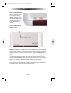
MRF-300 Manual.qxd 1/14/2005 12:40 PM Page 10 MRF-300 BASE STATION Click on the “cell” for the first identical TV, by crossing the device row with the Signals column. Signal Column TV1 Device Row Select RF from the three options shown for EACH of the identical TV’s.You may leave the other components of the system set to IR & RF.
MRF-300 Manual.qxd 1/14/2005 12:40 PM Page 11 MRF-300 BASE STATION Programming For Multiple Equipment Locations You can operate up to 15 different equipment locations, each with an MRF300 assigned a unique Receiver ID#. You program each of your remotes to talk to the equipment locations you want by assigning each of your devices to a receiver.
MRF-300 Manual.qxd 1/14/2005 12:40 PM Page 12 MRF-300 BASE STATION Frequently Asked Questions Can I use flasher/emitters that I have already installed in the system to connect to the MRF-300? Yes, the flashers are compatible if they use 3.5mm mono mini plugs with the same polarity (Tip is data, sleeve is ground). I am getting inconsistent operation regardless of flasher level or position. Some components are easily overloaded with IR from nearby flashers.
MRF-300 Manual.qxd 1/14/2005 12:40 PM Page 13 The Complete Control Remote Control System 500 Mamaroneck Avenue, Harrison, NY 10528 Phone: (914) 835-4484 Fax: (914) 835-4532 www.universalremote.