MRX-1 Installation Manual Network Base Station COMPLETE CONTROL ™ Universal Remote Control®
MRX-1 Installation Manual ©2010 Universal Remote Control, Inc. The information in this manual is copyright protected. No part of this manual may be copied or reproduced in any form without prior written consent from Universal Remote Control, Inc. UNIVERSAL REMOTE CONTROL, INC. SHALL NOT BE LIABLE FOR OPERATIONAL, TECHNICAL OR EDITORIAL ERRORS/OMISSIONS MADE IN THIS MANUAL. The information in this manual may be subject to change without prior notice.
TABLE OF CONTENTS Introduction 1 Features and Benefits 2 Parts Guide 2 Front and Rear Panel Descriptions 3 Network Installation 4 Optimizing IR Flasher Levels 5 Integrating Optional RFTX-1 to control URC LIghting 6 Integrating Optional Video or Voltage Sensors 7 Integrating RS-232 and Relays 10 Network Discovery 13 Overview of IR Routing 16 Network or RF Setup in CCP 16 IR over Narrow Band via Optional RFX-250 18 Connecting multiple MRX-1’s via RF Out 20 Frequently Asked Questio
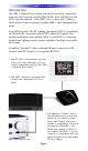
MRX-1 BASE STATION Introduction The MRX-1 Network Base Station receives IR and Serial commands from any URC Network Controls (like the KP-4000, MX-6000 or MX5000) over the network. Each MRX-1 has a unique MAC Address, which allows correct routing to multiple MRX-1 units throughout the home. In installations with URC RF Lighting, the optional RFTX-1 transmitter will transmit RF commands from all URC Network Control’s.
MRX-1 BASE STATION Features and Benefits The Bridge for Network Remotes and Keypads The MRX-1 enables IR and RS-232 devices to be controlled by URC Network Controls. 2-Way RS-232 Thermostats, Security Systems, Home Theater AVRS and Multi-Zone Matrixes Via the unique URC 2-Way database installers can drag and drop 2-Way pre-programmed modules into any URC Network Control powered by the MRX-1’s two RS-232 ports.
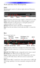
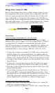
MRX-1 BASE STATION Front and Rear Panel Descriptions Front The front panel consists of 4 indicator lights which will illuminate when in use. Power Status Reset: Bottom Ethernet Sensor Power: Illuminates when the power supply is connected to an outlet Status: Flashes in blue when an RF or Network signal is received. Sensor: Illuminates to indicate that it is sensing the presence of composite video or AC or DC voltage.
MRX-1 BASE STATION IR Outputs: Connect emitters for IR control of connected devices. RFTX Port: Dual port #6 for the RFTX-1 connecting cable or included sleeved IR emitter. RF IN: Connects to a optional single RFX-250 (refer to manual) RF Out: Used for daisy chaining MRX-1s for RF Operation (Refer to RFX-250 manual) RF ID: 15 unique RF ID's provide RF control and routing to multiple MRX-1’s in the same home. (RF ID #0, the interference "sniffing" position, is used to detect RF interference in the area.
MRX-1 BASE STATION Optimizing IR Flasher Levels Test a few commands for each device before fixing the flasher in place on the front panel of a device. Since TiVo, Replay TV, Satellite Receivers and Cable Boxes are all extremely sensitive to IR overload or saturation, you should test them thoroughly. Put up the on screen guide and test the navigation arrows. Compare operation via RF to the original remote control. Operation should be identical.
MRX-1 BASE STATION Integrating Optional RFTX-1 to control URC Lighting RFTX-1 The RFTX-1 provides control of the URC Lighting 1. Simply plug the RFTX-1 with the 10’ pink connecting cable (included with the RFTX-1) into the MRX-1 pink fixed port #6. 2. Set the RFTX-1 to either 418MHz or 433MHz. Select either 418MHz or 433MHz 3. Set the URC Lighting Device in the CCP Editor to Network and set the IR output to Port #6. 4. Download to the MX remote and begin controlling your lights.
MRX-1 BASE STATION Integrating Optional Video or Voltage Sensors Voltage Power Sensor VS-1006 The VS-1006 Voltage Power Sensor allows voltage output of a system component to be used to monitor that component’s ON/OFF status for power management when the device does not have discrete commands or a composite video output is not available for video sensing.
MRX-1 BASE STATION trol voltage out of the current sensor to the two-pin plug-in connector on the VS-1006. The VS-1006 can sense AC or DC so polarity is not critical. 3. Connect the 4-circuit mini plug from the VS-1006 to the sensor input on the MRX-1 rear panel. 4. Plug the power cord on the current sensing device into an unswitched AC outlet. 5. Once the system has been powered up, the VS-1006 Power LED should illuminate Red. 6. To test Voltage Sensing, turn the Sensed Device on.
MRX-1 BASE STATION Composite Video Input (A/V Receiver DVD, VCR input, etc) using a shielded RCA to RCA video cable with gold ends. 5. To Test Video Sensing, once the system has been powered up, turn the sensed device on. The Sensor LED on the MRX-1 front panel, should illuminate in Blue. Turn the Sensed device off. The LED should turn off. If not, check connections and confirm the device is not outputting a ‘black screen’ or some other video sync information when off. 6.
MRX-1 BASE STATION Integrating RS-232 and Relays RS-232 There are two versions of the RS232 cable. The RS232M has a male DB9 connector and the RS232F has a female DB9 connector. Be sure to verify the proper cable configuration by visually inspecting the RS232 terminal on the device to be controlled. Some devices will use other types of connectors such as RJ45 and mini jacks. Custom cables can be made using the pin-out for the MRX-1 jacks.
MRX-1 BASE STATION 4. Click on the MRX-1 in the Model Designer window. 5. Click on the "Properties" tab at the lower right side of CCP 6. Click on RS-232 Port #1 on the actual MRX-1 image. 7. The Port 1 RS-232 Properties appear in the Properties tab. 8. Set the Baud Rate, Data, Parity and Stop Bits for the connected RS-232 component. (The manufacturer of the RS-232 component will provide the correct values.) 9. Click on RS-232 Port 2 and repeat the process if it will be controlling a component RS-232.
NC (Normally Closed) 1. For a device that PROVIDES VOLTAGE for use with a switch closure: a. Connect the +V Terminal on the controlled device to the Relay NC Terminal on the MRX-1 rear panel, using one of the included Three-pin plug-in connectors. b. Connect the GROUND Terminal on the controlled device to the RELAY COM Terminal using the same plug-in connector. 2. For a device that REQUIRES EXTERNAL CONTROL VOLTAGE: a. Splice the ends of a 12 volt wall adapter and connect it to the Relay COM Terminal. b.
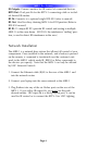
MRX-1 BASE STATION Network Discovery Adding a MRX-1 in CCP, modifying it’s Settings and testing RS-232 and Relay Commands. 1. Inside the CCP editor, select Program then Configure Home. 2. Add a MRX-1 base station and the properties window opens. 3. Type in a descriptive Name for the MRX-1 unit and select a RFID if using a RFX-250. 4. Either type in the MAC address which can be found on a sticker located on the bottom of the unit or click on the Discover button. Status 5.
MRX-1 BASE STATION 6. Now the MRX-1’s MAC address will populate the MAC address field. 7. Within the Port Information field, type in the devices designated to each IR and Serial port. 8. Press the Status button to open the Status and Firmware window. 9. The Status and Firmware window opens to reveal the current description, MAC ID, IP Address, RFID, Date and Time, Firmware version and update button.
MRX-1 BASE STATION 10. From the Status window, press the Settings button to open the Settings window. 11. The Settings window allows changes to be made to the description name, a dynamic or static IP address, or the Date & Time. Press Save to return to the Status window. 12. From the Status window, press the Test button to open the Test window. 13. The Test window provides realtime RS-232 and Relay command testing. Press Ok to return to the Status screen.
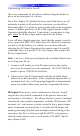
MRX-1 BASE STATION Overview of IR Routing There are several considerations to take into account when you are installing an MRX-1 to control an array of identical components: 1. Each identical component must receive IR commands ONLY from a dedicated Flasher affixed to its front panel or a rear panel direct IR input. The SIGNAL of the remote should be set to Network or RF ONLY for each identical component. IR can still be utilized for other devices in your system! 2.
MRX-1 BASE STATION Select Network or RF (for optional RFX-250) from the three options shown for EACH of the identical TVs. You may leave the other components with no flashers set to IR. 3. Select a Receiver to Control Identical Devices Choose a Base station to send commands over the Network or via RF to control multiple components. 4.
MRX-1 BASE STATION IR Over Narrow Band via Optional RFX-250 Note: RF remotes via RFX-250 can only control IR components. RS232, Relay and Sensor control are not available to RF remotes. 1. Power on all AV components, lower all dimmers to 50% and power on anything that may create RF Interference (particularly devices with high speed microprocessors or hard drives). 2. Check that the address wheel on the back of the MRX-1 is set to ID#0 (the interference “sniffing” position).
MRX-1 BASE STATION 5. Observe the RF LED of the RFX-250. Cup your hand over the RFX-250’s RF LED. If it is glowing or flickering you must relocate the RFX-250 to a location where the LED does not flicker. 6. Observe the STATUS LED of the MRX-1. It is a little more sensitive than the RFX-250. If you see any flickering of this LED, move the RFX-250 to a new location.
MRX-1 BASE STATION Connecting multiple MRX-1’s via RF Out Multiple MRX-1 units can be daisy chained to control an unlimited amount of components in a home theater equipment rack. Follow the procedure below to daisy chain two or more MRX-1 units. 1. Connect the RFX-250 to the RF In 3.5 mm jack of the first MRX-1 unit. 2. Use another 3.5mm cable included with each MRX-1 to connect to RF Out of the first MRX-1 to RF In of the second. 3. Repeat Step 2 for multiple MRX-1 units.
MRX-1 BASE STATION Frequently Asked Questions Can I use flasher/emitters that I have already installed in the system to connect to the MRX-1? Yes, the flashers are compatible if they use 3.5mm mono mini plugs with the same polarity (Tip is data, sleeve is ground). It is important to notate the RFTX-1 shared port utilizes a sleeved emitter for long term use. I’m getting inconsistent operation regardless of flasher level or position. Some components are easily overloaded with IR from nearby flashers.
MRX-1 BASE STATION USA Limited Warranty Statement Your Universal Remote Control, when delivered to you in new condition, is warranted against defects in materials or workmanship as follows: UNIVERSAL REMOTE CONTROL, INC. warrants this product against defects in material or workmanship for a period of one (1) year and as set forth below.
Information To The User This equipment has been tested and found to comply with the limits for a Class B digital device, pursuant to part 15 of the FCC Rules. These limits are designed to provide reasonable protection against harmful interference in a residential installation. This equipment generates, uses and can radiate radio frequency energy and, if not installed and used in accordance with the instructions, may cause harmful interference to radio communications.
COMPLETE CONTROL ™ Universal Remote Control® 500 Mamaroneck Avenue, Harrison, NY 10528 Phone: (914) 835-4484 Fax: (914) 835-4532 www.universalremote.